Electric Vehicle Connector Design

Electric vehicles have been around a long time – over 100 years, in fact. Interest flared during the 1973 Arab Oil Embargo, which led to Congressional action in 1976 authorizing the Energy Department to support R&D into EV and hybrid vehicles. Even so, early vehicles had lamentable range and performance. By the time GM’s groundbreaking EV1 came along in 1996, though, at least the performance had improved; the EV1 boasted a 0 – 60 time of 7 secs, but still with a range of only 80 miles.
Now, though the revolution is in full swing with over 234,000 plug-in EVs and 3.3 million hybrids on the road in the US today. In contrast to the 12V battery systems used in traditional automobiles, a modern EV Li-Ion battery pack such as used on the Chevy Volt develops up to 390V.
The common unit used to measure engine performance is the horsepower (HP), which is equivalent to 750 watts of electrical power; the Volt’s primary traction electric motor/generator has a peak output of 111kW of electrical power, equivalent to 149HP. A high performance EV sports car could easily require more than 300 kW of electrical power. Using a 750V power inverter, that would be 400A, even before taking into account the varying phase alignment of applied voltage with applied current – in reality, the power equation is a more complex rotating vector calculation.
Such voltages and currents pose special challenges for EV connector manufacturers. To find out more about some of the design issues, I contacted Philip Desmond, Strategic Marketing Manager for Molex, who helped bring me up to speed.
High power EV connector safety
UL does not consider voltages below 60V DC hazardous enough to require special safety designs to prevent unintended human contact with connector pins. For higher voltages, there is the potential for serious, even fatal, injury, so a High Voltage Interlock (HVIL) circuit is an important addition.
An HVIL circuit is a separate closed circuit built into the connector design that is a mate-last/break-first type of connection. As an EV connector starts to disconnect, the HVIL circuit detects that movement and signals the power electronics to discharge high voltages present at the terminal below 60V before the final disconnection of the terminal, typically within a half second of the beginning of the connection break. Ideally, that results in no high voltages being present at the EV terminals when the connector is fully separated.
As a secondary safety strategy, EV mechanical designs require insulating material between the electrical contacts and potential human interfaces. The mechanical dimensions of the materials are small enough that a “standard” finger cannot make contact with the electrical voltage at the metal terminal if dangerous voltages are still present.
Thermal management
High current produces power losses that are proportional to the contact resistance between the mating surfaces of the connector. At 1 mΩ of contact resistance, a 400A current would produce 160 watts (I2 R) of power lost as additional connector heat.
Automotive connectors must survive in environments with broad temperature extremes that may range from -40C to 105C. In the connector industry, it is standard to limit the application-induced temperature rise on the terminals to no more than 30 degrees C to maintain the desired mechanical tolerances as the terminal material expands due to internal heating.
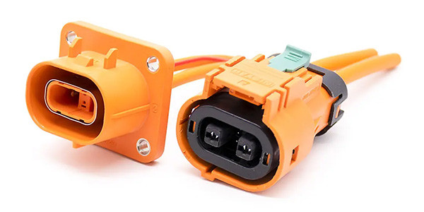
A 160W power loss can easily create such a temperature rise, if the heat cannot be dissipated effectively through the connector to the surrounding environment. The connector in Figure 1 is designed to have less than 50 µΩ of contact resistance.
Contact resistance
Contact resistance is also a function of the force compressing the two connecting components of a terminal together. High compression forces result in a high insertion force, which is undesirable in a modern automotive manufacturing environment, so Molex use proprietary lubricants to both protect the surfaces of the contacts and reduce insertion force.
The shape, design, material, and plating of the terminals are also important design considerations in reducing insertion force.
High voltages can introduce a phenomenon known as dendritic growth, where certain metal ions are encouraged to move from one physical position to another due to the force of the electric potential between the connector terminals. Metal migration can eventually result in a short circuit between the connector terminals. Prevention requires a careful selection of metal compounds used for plating the terminals.
High voltages can also introduce arcing between the terminals and ground connections due to the breakdown of the insulating properties of plastics and air in the presence of moisture or other environmental contaminants. Preventing these effects requires a larger mechanical spacing of the contacts relative to the circuit ground as part of the design. This is commonly known as providing the necessary clearance and creepage.
EV space and weight
Mechanical dimensional requirements can result in EV connectors that are larger and heavier than desirable, which works contrary to the industry trend to smaller, lighter and more economical electronic controls and connectors. Managing the physical size and mass needed to conduct high currents is one of the more significant challenges in designing EV connectors.
The metal wires used in EV applications must maintain high electrical conduction and efficiency. Copper is the usual choice because of its low cost, high conductivity, ductility (which allows it to be more flexible during installation), and the fact that it conducts heat well. Unfortunately, copper is also relatively heavy.
Mechanical stress load, EMI/EMR
During vehicle operation the movement of the significant copper wire mass results in high vibration stress loads on the connector body. Automotive applications, where power components are exposed to road vibration and environmental conditions such as dust, water, solvents, steam cleaners, etc., additionally require strategies to maintain protective seals along the cable and connector body-to-power enclosure interface. The design goal is to keep environmental contaminants out of the power electronics enclosure, while preventing stresses caused during vehicle operation from damaging the connector body, power electronic enclosure, terminals or the wire.
Most EV applications control the power applied to the motor by pulse-width-modulating (PWM) the current which introduces high electromagnetic radiated and conducted emissions, so the wire must be shielded to minimize EMC issues, further increasing the weight.
Life-cycle reliability
For decades, the automotive method of choice for assembling terminals to large copper cables has been to crimp the terminal (lug) onto the cable. The crimping process inserts high stress on the terminal body, deforming its shape and gripping the cable tightly. EV systems pulse high power through the joint between the cable and connector terminal. The cycle of localized heating and cooling of the interface and joint causes minute expansion and contraction of the material.
Thousands of hours of such operation can cause long-term degradation of the joint contact resistance between the cable and the terminal, which can eventually result in connection failure requiring cable/connector replacement.