Connector manufacturer
Connector manufacturer
How Does an Automotive Electrical Distribution System Work? The Nervous System of the Modern Vehicle
The modern automobile is a marvel of engineering, often described as a rolling computer network. While engines and transmissions capture popular imagination, it is the Electrical Distribution System (EDS) that breathes life into today’s vehicles. This intricate network, akin to the human nervous and circulatory systems combined, is responsible for generating, storing, routing, protecting, and controlling electrical power to every electronic component. From starting the engine and charging your phone to enabling advanced driver-assistance systems (ADAS), the EDS is the silent, indispensable backbone. This article delves into the architecture, key components, operation, and evolving technologies of the automotive electrical distribution system.
The Core Architecture: A Mobile Power Grid
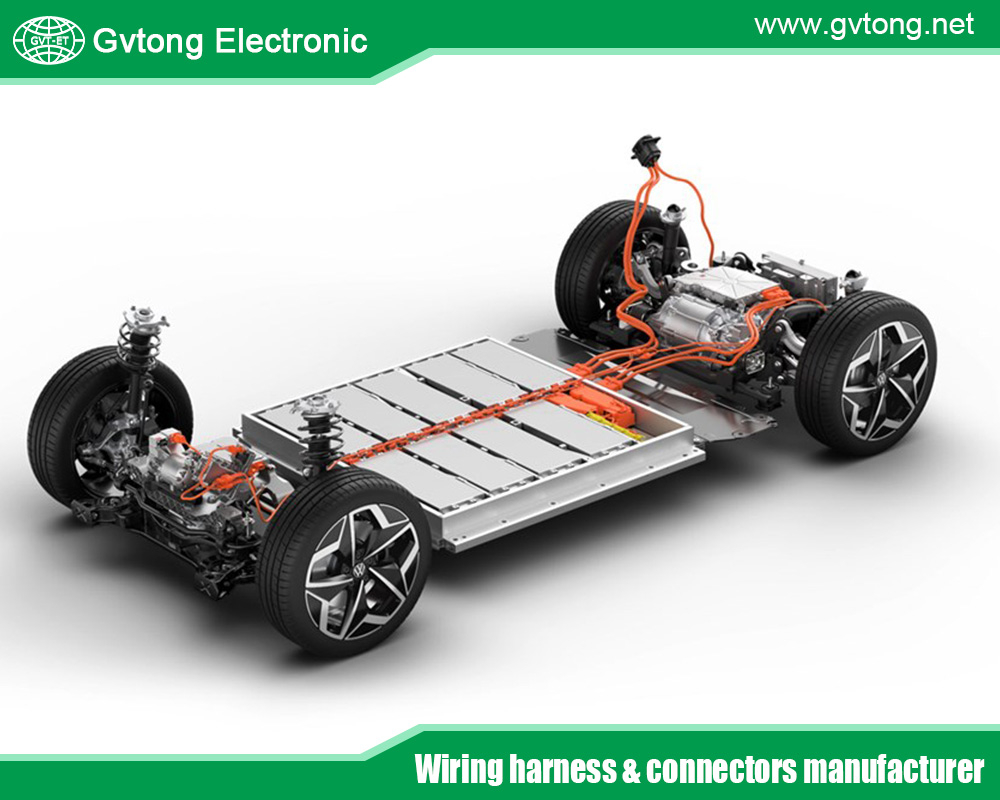
At its heart, an automotive EDS is a DC (Direct Current) system, traditionally operating at 12 volts, though 48V and high-voltage (400V/800V) systems are emerging for hybrids and electric vehicles. Its primary mission is twofold:
- Provide abundant, stable electrical power to all loads (consumers) under all operating conditions.
- Ensure safety and reliability by protecting against overloads, short circuits, and faults.
The system follows a fundamental architecture, which can be broken down into five key subsystems:
- Generation: The alternator.
- Storage: The battery.
- Distribution: Wiring harnesses, buses, and connectors.
- Protection: Fuses, circuit breakers, and relays.
- Control & Communication: Switches, electronic control units (ECUs), and data networks (like CAN Bus).
Key Components and Their Functions
- The Battery: The Power Reservoir
The lead-acid battery (with increasing use of AGM/EFB types) or lithium-ion battery in EVs serves critical functions:
- Engine Starting: Provides a massive surge of current (200-600 amps) to the starter motor.
- Voltage Stabilization: Acts as a buffer, smoothing out voltage spikes and drops from the alternator, protecting sensitive electronics.
- Power Supply When Off: Powers all systems when the engine is not running (e.g., security, keyless entry, infotainment memory).
- Backup Power: Supports electrical loads if the alternator fails or its output is exceeded.
- The Alternator: The Power Plant
Driven by the engine via a serpentine belt, the alternator is the primary source of power when the engine is running. It converts mechanical energy into AC electrical energy, which is immediately rectified to DC to charge the battery and supply the vehicle’s network. Modern smart alternators are controlled by the Engine Control Module (ECM) to optimize fuel efficiency by reducing electrical load during acceleration and increasing charging during deceleration (regenerative charging).
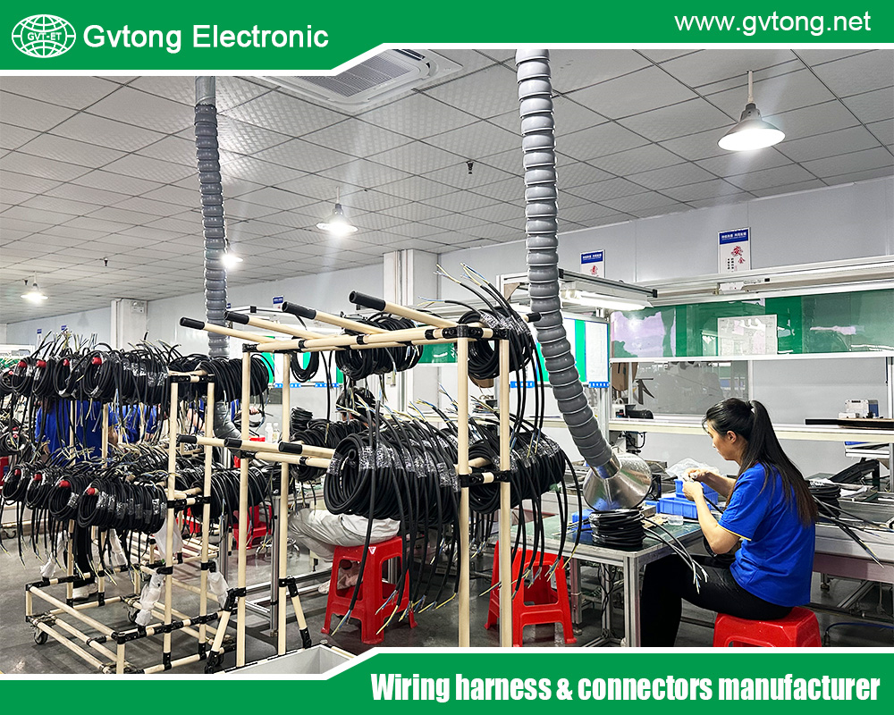
- Wiring Harnesses: The Arteries and Veins
The wiring harness is the physical manifestation of the distribution network. It is a complex, vehicle-specific assembly of wires (of precise gauges for current-carrying capacity), terminals, and connectors, bundled together with tapes and conduits. It is meticulously designed and routed through the vehicle’s body to connect every component. Key elements include:
- Primary Cables: Very thick cables for high-current paths (battery to starter, battery to chassis/engine ground).
- Insulation & Shielding: Protects against abrasion, heat, and electromagnetic interference (EMI), which is crucial for sensor signals.
- Connectors: Sealed, locking connectors ensure reliable, corrosion-resistant connections.
- The Fuse Box (Power Distribution Center): The Security Hub
The fuse box, or Integrated Power Module (IPM), is the central hub for circuit protection and power routing. It is typically located in the engine bay and/or cabin. Its roles are:
- Circuit Protection: Contains fuses—deliberately weak links that melt and break the circuit during an overload or short circuit, preventing wire damage or fire.
- Power Distribution: Receives high-current power from the battery and alternator via heavy-gauge wires and distributes it to various smaller circuits via fusible links or maxi-fuses.
- Relay Control: Houses relays, which are electrically operated switches. They allow a low-current circuit (e.g., from a dashboard switch) to control a high-current circuit (e.g., headlights, fuel pump), protecting the switch and control wiring.
- Relays: The Heavy-Duty Switches
Relays are electromagnetically operated switches. A small current from a control switch energizes a coil inside the relay, which closes a set of internal contacts capable of carrying much larger currents. This design keeps high currents away from the driver’s controls and confines them to more robust, protected pathways.
- Grounding: The Return Path
Often overlooked, the ground system is equally vital. The vehicle’s metal chassis and body act as a common return path (ground) to complete every electrical circuit. Secure, clean, and tight ground connections at multiple points are essential to prevent erratic electrical behavior, voltage drops, and component malfunction.
- Electronic Control Units (ECUs) and Networks: The Brain and Nerves
Modern vehicles contain dozens of ECUs—microprocessor-based controllers for specific functions (engine, transmission, brakes, body, etc.). These ECUs are both consumers and controllers of electrical power. They communicate with each other via serial data networks:
- CAN Bus (Controller Area Network): The backbone, a robust, twisted-pair wire network that allows ECUs to share data (e.g., engine RPM to the instrument cluster).
- LIN Bus (Local Interconnect Network): A simpler, cheaper subnet for low-speed devices like window switches or sensors.
- MOST (Media Oriented Systems Transport) / Ethernet: Used for high-bandwidth infotainment and ADAS data.
The power distribution automotive electrical distribution system must provide clean, stable power to these sensitive digital components, and the data networks run parallel to the power distribution, forming the vehicle’s complete “nervous system.”
How the System Works: A Dynamic Workflow
The operation of the EDS is a dynamic interplay between components, varying with the vehicle’s state.
State 1: Ignition Off (Battery Mode)
- Power flows from the battery to a set of “always hot” circuits.
- These power memory-dependent systems: the clock, security system, keyless entry receiver, and body control module in sleep mode.
- Current draw is minimal (milliamps to a few amps), known as parasitic drain.
State 2: Ignition On / Engine Cranking (Critical Load Mode)
- Turning the key or pressing “Start” activates the ignition switch circuit (now often a signal to the Body Control Module).
- Power is routed to the engine control module, fuel pump, and ignition system.
- A massive surge is sent to the starter motor solenoid (via the starter relay), engaging the starter and drawing 200+ amps from the battery.
- Most other high-load systems (headlights, HVAC blower) are temporarily inhibited to conserve battery power for cranking.
State 3: Engine Running (Generation & Distribution Mode)
- Once the engine runs, the alternator begins generating power.
- The alternator’s output voltage (typically 13.5V – 14.5V) is slightly higher than the battery’s nominal 12.6V, causing it to charge the battery and supply the entire vehicle’s electrical load.
- The battery transitions to a load-balancing and stabilization role.
- The Power Distribution Center routes power from the alternator/battery junction to all active circuits via fuses and relays.
- ECUs, now fully powered, communicate via networks, monitoring sensors and activating actuators (fuel injectors, valves, motors).
State 4: Managing Electrical Load
The vehicle’s electrical demand is highly variable. Idling with headlights, rear defroster, and the A/C blower on can demand over 100 amps. The ECM and Body Control Module (BCM) often perform load shedding—temporarily disabling non-critical loads (like seat heaters) to prioritize critical systems and prevent overloading the alternator.
Protection Strategies: Ensuring Safety
Safety is engineered into every layer:
- Fuses & Circuit Breakers: Protect wiring from overload. They are sized just above the normal operating current of the circuit they protect.
- Fusible Links: Short sections of special, undersized wire that melt under sustained overload, protecting main feeder lines.
- Relays: Isolate control circuits from high-power loads.
- Ground Fault Interrupters (in EVs/HEVs): Monitor for current leakage in high-voltage systems.
- Physical Protection: Conduits, grommets, and loom tape protect harnesses from heat, sharp edges, and vibration.
The Future: Evolution of Electrical Distribution
The demands of electrification, autonomy, and connectivity are driving radical changes:
- Increased Voltage: 48V Mild-Hybrid Systems reduce current (and thus copper weight/power loss) for heavy loads like electric turbochargers, active suspension, and high-power regenerative braking. 400V/800V Architectures in EVs are essential for fast charging and powerful drive motors.
- Zonal Architecture: Moving away from a central fuse box, zonal controllers are placed around the vehicle. These smart modules, connected via high-speed Ethernet, control all devices in their physical zone (e.g., front-left), receiving power via simpler, thicker cables and communicating via data. This reduces wiring complexity and weight.
- Advanced Power Management: Sophisticated algorithms predictively manage energy between the battery, alternator/motor-generator, and loads for maximum efficiency.
- Solid-State Power Distribution: Replacing traditional fuses and relays with solid-state switches controlled by software. This allows for programmable protection curves, real-time current monitoring, and remote diagnostics.
- Increased Redundancy: For autonomous driving, critical systems (braking, steering, sensors) require fully redundant power paths to ensure operation in case of a single point of failure.
Conclusion
The automotive electrical distribution system is a masterpiece of systems engineering—a complex, reliable, and safe mobile grid. It has evolved from a simple circuit for ignition and lighting into a sophisticated, computer-managed network that is fundamental to every vehicle function. Understanding its components—from the battery and alternator to the fuse box, wiring, and ECUs—reveals the elegant logic that powers our vehicles. As the industry accelerates toward electrification and autonomy, the EDS will continue to be the critical enabler, transforming from a passive distribution network into an intelligent, adaptive, and highly resilient nervous system for the next generation of mobility. Its design and health remain as crucial as the engine itself, dictating the reliability, functionality, and safety of the entire vehicle.
For more about how does an automotive electrical distribution system work? The nervous system of the modern vehicle, you can pay a visit to Gvtong at https://www.gvtong.net/ for more info.


