Connector manufacturer
Connector manufacturer
Battery Management System (BMS) Scalable Connectors for Modular Battery Designs
The global transition towards electrification—spanning electric vehicles (EVs), renewable energy storage, portable electronics, and industrial applications—has placed unprecedented demands on battery technology. A critical paradigm shift enabling this evolution is the move from monolithic, fixed battery packs to modular battery designs. These systems assemble multiple, smaller, self-contained battery modules into a larger pack, offering unparalleled advantages in manufacturing, maintenance, scalability, and serviceability.
At the heart of every safe, efficient, and reliable battery module lies the Battery Management System connector, the electronic brain responsible for monitoring, protecting, balancing, and reporting the state of the battery. However, the true enabler of a modular architecture is not just the BMS itself, but the often-overlooked physical and data highway that interconnects them: the scalable connector system. This article delves into the critical role, design challenges, and technological innovations of BMS connectors in scalable, modular battery systems.
The Imperative for Modularity and Scalability
Modular battery designs address several key industry challenges:
-
Manufacturing & Logistics: Standardized modules simplify production, reduce costs, and ease handling.
-
Flexibility & Scalability: Packs can be configured with different numbers of modules to offer varying energy (kWh) and power (kW) ratings from the same core components.
-
Serviceability & Second Life: A faulty module can be isolated and replaced without discarding the entire pack. Post-vehicle life, modules can be tested and repurposed for less demanding energy storage applications.
-
Thermal Management: Smaller modules can be more effectively cooled or heated than a single large block of cells.
For the BMS scalable connectors, this modularity typically translates into a distributed or master-slave architecture. A Master BMS handles high-level communication with the vehicle or host, while multiple Slave BMS or Cell Monitoring Units (CMUs) are embedded within each module, managing a subset of cells. The inter-module connections must carry not only high-current power but also vital low-voltage signals for measurement, control, and communication.
The Connector as a Critical System Component: More Than Just a Plug
In a modular BMS context, connectors are far more than passive components. They are critical points of system integrity, responsible for:
-
Power Transmission: Carrying the main DC current from series- and parallel-connected modules.
-
Signal Integrity: Transmitting precise analog voltage and temperature measurements (often in the millivolt and milliamp range) without introducing noise.
-
Data Communication: Facilitating robust, error-free digital communication buses (e.g., CAN FD, SPI, daisy-chained isolators) between Master and Slave units.
-
Safety Isolation: Providing adequate creepage and clearance distances to prevent high-voltage tracking to low-voltage circuits.
-
Mechanical Latching: Ensuring a secure, vibration-resistant connection that cannot be accidentally disconnected under force.
-
Serviceability: Enabling safe “hot-plug” capabilities or clear sequencing (make-first, break-last for safety grounds) for maintenance.
A failure in any of these functions can lead to catastrophic outcomes, from inaccurate state-of-charge estimation and reduced lifespan to complete system shutdown, thermal runaway, or electrical fire.
Key Design Challenges for Scalable BMS Connectors
Designing a connector system for scalable BMS applications requires navigating a complex web of electrical, mechanical, and environmental requirements.
1. Electrical Performance & Contact Design:
-
Current Rating: Must handle continuous and peak module currents. Scalability often means using the same connector family across modules of different capacities, requiring contacts rated for the highest expected system current.
-
Contact Resistance: Extremely low and stable contact resistance is non-negotiable. High resistance leads to I²R power losses, localized heating, and voltage measurement errors. Materials like copper alloys with silver or tin plating are standard.
-
High-Voltage (HV) Capability: As system voltages push beyond 800V and even 1000V for EVs, connectors must manage higher dielectric strength and prevent corona discharge. This involves sophisticated insulation materials and geometry design.
2. Mixed-Signal & Shielding Requirements:
This is a paramount challenge. A single connector often must combine:
-
High-Voltage Power Pins
-
Low-Voltage Sense Lines (high-impedance, sensitive to noise).
-
Digital Communication Pairs (differential signals like CAN).
-
Safety & Interlock Circuits.
Cross-talk between power lines and sense lines can corrupt cell voltage measurements. Effective shielding—using dedicated shield layers, compartments within the connector, or separate hybrid connectors for power and signal—is essential. Some advanced designs integrate ferrite elements directly into the connector housing to suppress high-frequency noise.
3. Mechanical & Environmental Robustness:
-
Vibration & Shock: Automotive and mobile applications demand compliance with rigorous standards (e.g., USCAR, LV214). Connectors must maintain electrical continuity under constant vibration.
-
Ingress Protection (IP Rating): Typically requiring IP67 or IP6K9K to withstand dust, water jets, and pressure washing.
-
Thermal Cycling: Connector materials must have matching coefficients of thermal expansion to maintain seal integrity and contact force across extreme temperature ranges (-40°C to +125°C).
-
Mating Cycle Durability: Must withstand hundreds of mating cycles for factory assembly and potential field service.
4. Safety & Sequencing:
-
HVIL (High-Voltage Interlock Loop): A safety-critical circuit that runs through all HV connectors. If a connector is disconnected, the HVIL circuit is broken, commanding the BMS to open contactors and discharge HV bus capacitors before physical separation of power pins occurs.
-
Touch Protection & Coding: Physical design must prevent human contact with live parts. Mechanical keying prevents mismating of incompatible modules.
-
Grounding (PE) First / Last Break: The protective earth connection should be the first to make and the last to break during mating/unmating, ensuring a safe discharge path.
Innovations in Connector Technology for Scalability
To meet these challenges, connector manufacturers are innovating rapidly:
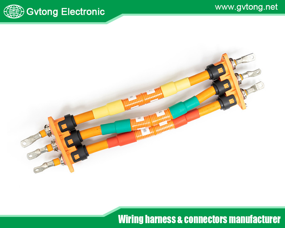
1. Hybrid & Modular Connector Systems:
Instead of using separate connectors for power, signal, and data, hybrid connectors integrate all functions into a single housing. For scalability, manufacturers offer modular systems where a base frame accepts different insert configurations (e.g., 2 power pins + 12 signal pins, or 4 power pins + 8 signal pins). This allows a single connector platform to serve multiple module variants within a product family, simplifying inventory and assembly.
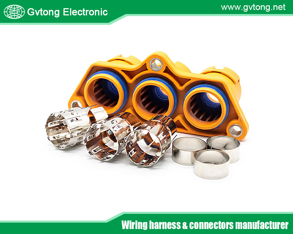
2. Advanced Contact Systems:
-
Hyperboloid Contact Technology: Uses a cage of twisted wires that provide multiple, redundant points of contact. This offers very low resistance, excellent vibration resistance, and high mating cycle life.
-
Canted Coil Spring Contacts: Provide a reliable gas-tight connection with low insertion force, ideal for blind mating in module stacking configurations.
3. Integrated Electronics & “Smart Connectors”:
The frontier of connector technology involves embedding simple electronics within the connector housing itself. This can include:
-
Localized ADC or filtering for analog sense lines to digitize signals close to the source, reducing noise susceptibility over the harness.
-
Passive balancing resistors switched by the Slave BMS but housed within the connector assembly.
-
Unique ID resistors or ICs that allow the Master BMS to automatically identify module type, position, and capability upon connection—a key feature for true plug-and-play scalability.
4. Materials Science:
-
High-Temperature Plastics: Liquid crystal polymer (LCP) and polypothalamide (PPA) resins maintain structural integrity and dielectric properties at elevated temperatures.
-
Advanced Sealants & Greases: Silicone gels and fluorinated greases protect contacts from corrosion and provide stable contact resistance in humid environments.
Standardization and System Integration
The lack of universal standards for BMS module interfaces is a current industry hurdle. While standards like ISO 6469-3 cover HV safety, the pin-out, communication protocol, and mechanical interface are often proprietary. This locks customers into a single supplier and complicates second-life logistics.
Forward-thinking companies and consortiums are pushing for standardized modular interfaces. A well-defined standard would specify:
-
Mechanical form factor and keying.
-
Pin functions and assignments (Power+, Power-, Sense+, Sense-, CAN H/L, HVIL, etc.).
-
Communication protocol and addressing scheme.
-
Safety sequencing logic.
Such a standard would decouple module and pack development, fostering innovation, reducing cost, and creating a true circular economy for battery modules.
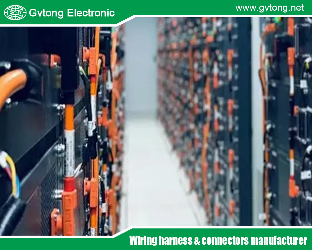
Case Study: Connector Strategy in a Scalable Stationary Storage System
Consider a grid-scale battery energy storage system (BESS) designed with 5kWh modules. Each module contains its own Slave BMS, 14 Li-ion cells in series, and a thermal sensor.
-
Connector Requirements: One 2-pin HV power connector (rated for 200A), one mixed-signal connector.
-
Mixed-Signal Connector Pins:
-
2 Pins: Cell voltage sense taps (highest and lowest in the module string).
-
2 Pins: Temperature sensor input.
-
2 Pins: Isolated CAN bus for communication.
-
1 Pin: HVIL circuit.
-
1 Pin: Module presence/identification.
-
2 Pins: Low-voltage power supply for the Slave BMS.
-
-
Scalability: The pack is assembled by stacking modules side-by-side. Busbars connect the HV power connectors in series. A single communication cable daisy-chains through the mixed-signal connectors of all modules. The Master BMS, upon startup, pings each module’s ID pin to understand the pack configuration (number of modules, their order, and type) automatically. The connector’s robust shielding ensures that the 400V+ HV ripple does not interfere with the 3.3V CAN signals running in parallel.
Conclusion
As battery systems evolve towards greater modularity, flexibility, and intelligence, the humble connector rises from a commodity component to a strategic system-level enabler. The design of scalable BMS scalable connectors sits at the intersection of high-power electrical engineering, low-noise analog design, robust mechanical engineering, and stringent safety science.
The ongoing innovations in hybrid designs, smart features, and materials are directly contributing to more reliable, efficient, and sustainable energy storage solutions. Ultimately, the goal is to achieve a seamless, plug-and-play battery ecosystem, where modules can be assembled, serviced, and repurposed with the ease of installing a component in a desktop computer. To realize this vision, continued focus on and investment in advanced, standardized, and scalable BMS connector technology is not just important—it is imperative.
For more about battery management system (BMS) scalable connectors for modular battery designs, you can pay a visit to Gvtong at https://www.gvtong.net/ for more info.
-

GE Series-10PIN Right Angle Connector Socket
-

Energy storage connector 8.0mm
-
-Cores-1")
GD Series – Combined Power Connector – (2+1+5) Cores
-

Automotive injection molded parts
-
-1")
4-pin power connector (35A)
-

GE Series-39-core rectangular connector-socket
-
")
Signal connector – waterproof, three-row, 8-pin
-
")
Signal connector – waterproof, three rows, 23 cores