Connector manufacturer
Connector manufacturer
How Does a High-Voltage Connector in an Automotive Application Work?
As the automotive industry undergoes its most significant transformation in a century, the shift from internal combustion engines to electric vehicles (EVs) and hybrid electric vehicles (HEVs) has created a new technological paradigm. At the heart of this electric revolution lies a critical, yet often overlooked, component: the high-voltage (HV) connector. These are not mere plugs and sockets; they are sophisticated electromechanical systems engineered to safely, reliably, and efficiently manage the lifeline of an EV—its high-voltage electrical energy. This article delves into the fundamental principles, design complexities, key components, and stringent requirements that govern how an automotive high-voltage connector works.
Introduction: The Veins of the Electric Vehicle
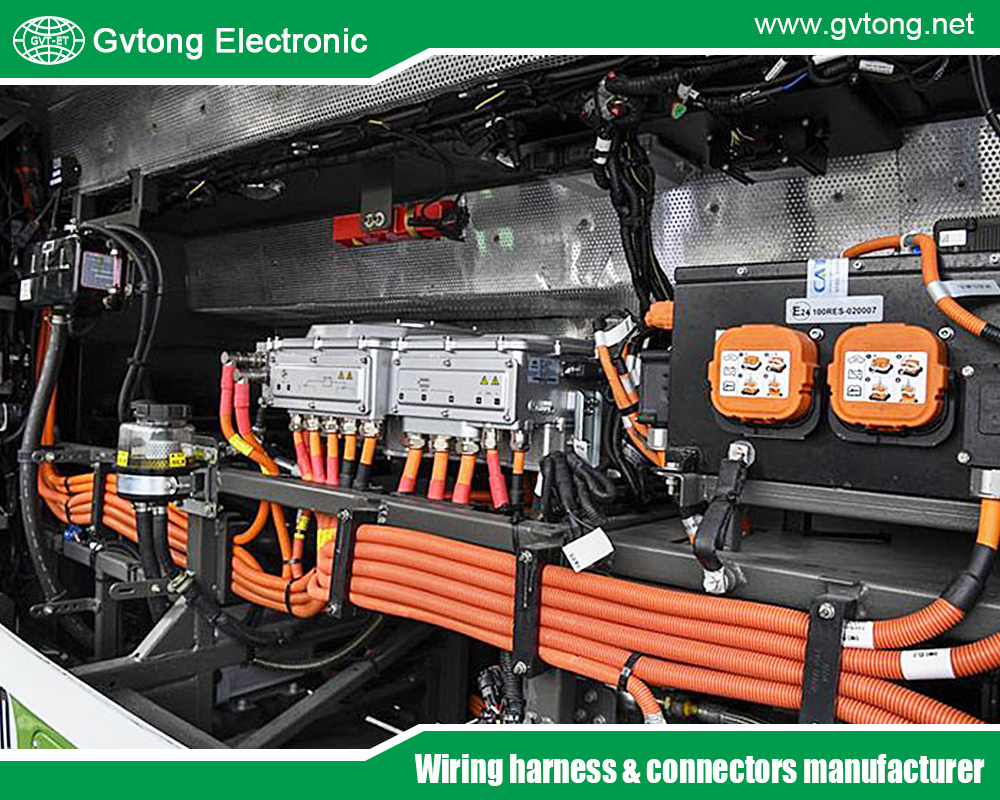
Modern electric vehicles operate with voltage levels typically ranging from 400V to 800V, with some platforms pushing towards 1000V. Currents can exceed 300A, especially during peak acceleration or fast charging. This electrical system—comprising the battery pack, electric traction motor(s), power electronics (inverter, DC-DC converter), and the onboard charger—forms the vehicle’s “high-voltage circulatory system.”
High-voltage connectors are the joints and valves in this system. They facilitate the modular assembly of the vehicle, enable serviceability, and ensure that energy flows uninterrupted under the most demanding conditions: from -40°C to +125°C temperatures, constant vibration, exposure to fluids, and mechanical shock. Their primary mission is threefold: to conduct power with minimal loss, to protect users and technicians from electric shock, and to maintain integrity over the vehicle’s lifetime.
Fundamental Operating Principles and Key Requirements
Unlike low-voltage automotive connectors, HV connectors are governed by a set of non-negotiable imperatives:
- Safety First (HVIL): The paramount concern is preventing accidental contact with live parts. This is primarily achieved through the High-Voltage Interlock Loop (HVIL). HVIL is a low-current, safety-monitoring circuit that runs through every HV connector. When a connector is mated, the HVIL circuit is completed, signaling to the vehicle’s control units that the system is intact and safe to energize. If a connector is disconnected before the system is shut down, the HVIL circuit breaks first (through a shorter pin), commanding an immediate and safe power-down before the main high-voltage contacts separate. This is the connector’s “first, break; last, make” safety protocol.
- Reliability & Durability: Connectors must maintain a stable, low-resistance electrical connection for over 10,000 mating cycles (for serviceable parts) and withstand the vehicle’s entire operational life (often 15+ years) for sealed connections. This requires exceptional materials and contact design.
- Environmental Sealing: Rated at a minimum of IP6K7 (dust-tight and protected against temporary immersion) and often IP6K9K (for high-pressure, high-temperature washdowns), connectors must exclude water, dust, and contaminants that could cause tracking (unwanted current flow along surfaces) or corrosion.
- Electromagnetic Compatibility (EMC): High-current, switched power electronics generate significant electromagnetic interference (EMI). Connectors must provide 360° shielding to contain this EMI within the cable and connector system, preventing disruption to onboard electronics (like ADAS sensors) and external communications.
Anatomical Breakdown: Core Components and Their Functions
A typical automotive HV connector is a marvel of integrated engineering. Let’s dissect its key components:
- Electrical Contact System
- Contact Terminals (Male & Female): Usually made from precision-machined or stamped copper alloys (e.g., brass, bronze) with high-grade silver or tin plating. This ensures excellent conductivity, low contact resistance, and resistance to corrosion and fretting (micro-movement induced wear).
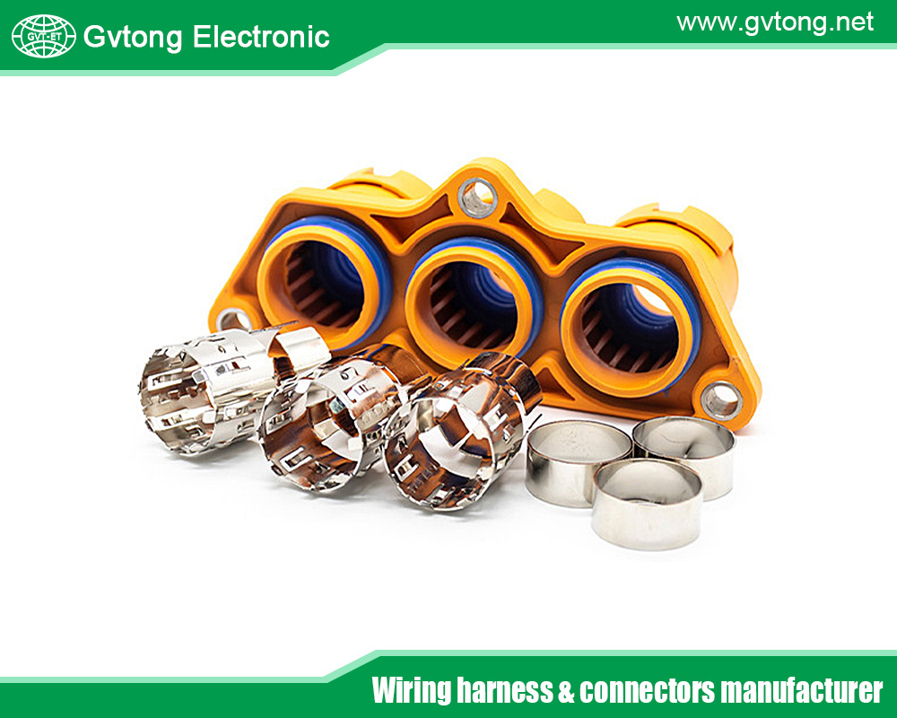
- Contact Geometry: The design is crucial for achieving high normal force (the spring pressure holding contacts together). Common types include:
- Pin & Socket: A robust, simple design for high currents.
- Hyperboloid (Cage-Tension) Contacts: A sleeve made of multiple wires arranged in a hyperboloid shape. The pin insertion causes the wires to stretch and wrap tightly around it, providing multiple points of contact, very high normal force, and exceptional vibration resistance.
- Contact Housing: Made from high-temperature, high-strength engineering plastics (e.g., PBT, PPA), it precisely aligns and insulates the terminals.
- Insulation and Dielectric Withstanding
Preventing electrical breakdown between contacts and to ground is critical.
- Creepage Distance: The shortest path for current to travel along the surface of the insulator between conductors. Contaminants (moisture, dust) can reduce surface resistance.
- Clearance Distance: The shortest straight-line distance through the air between conductors.
- Dielectric Material: The plastic housing and any internal barriers are designed to maximize these distances within a compact form factor. Materials must have high Comparative Tracking Index (CTI) to resist forming conductive paths on the surface.
- Shielding and EMC Management
- Shielding Shell: A metal shell (often aluminum or stainless steel) encases the entire connector assembly.
- Shielding Termination: The braided shield of the HV cable must be connected 360° circumferentially to this shell via a clamp or ferrule. This creates a continuous Faraday cage, directing EMI/EMC noise back to the source ground. Any gap acts as an antenna, radiating interference.
- Mechanical Locking and Sealing
- Primary Lock: A robust latching mechanism (e.g., lever, push-pull, or screw-lock system) prevents accidental unmating due to vibration or cable pull. It often provides audible and tactile feedback (a “click”).
- Secondary Lock: A separate device (often an orange slider or clip) that locks the terminals into the housing, preventing them from backing out.
- Seals: Multiple elastomeric seals (silicone, FKM fluoroelastomer) are employed:
- Interface Seal: Seals between the two connector halves.
- Wire Seal: Provides a radial seal around each individual cable.
- Housing Seal: Seals the housing itself.
- Thermal Management
High current generates heat (Ploss=I2RPloss=I2R). Connectors must dissipate this heat effectively.
- Material Choice: Thermally conductive plastics or metal housings help.
- Contact Design: Larger contact areas and higher normal force reduce contact resistance, the primary source of heat.
- Active Cooling: In some ultra-high-power applications (e.g., >500A), connectors may integrate liquid cooling channels.
The Mating Sequence: A Choreography of Safety and Connection
The mating process of an HV connector is a carefully orchestrated sequence:
- Alignment and Pre-Mating: The connector halves, often with guiding shrouds, align. The HVIL pins are recessed or designed to engage last.
- Mechanical Lock Engagement: The primary lock (e.g., a lever) begins to engage, pulling the halves together against the force of the seals.
- Sealing Surface Contact: The primary environmental seal makes contact, isolating the internal cavity.
- Shield Bridging: The metal shielding shells make first electrical contact, maintaining EMC integrity.
- Main Power Contact Mating: The high-current male and female contacts engage under controlled force.
- HVIL Circuit Completion: Finally, the shorter or specially sequenced HVIL contacts mate, closing the safety loop. Only now does the Vehicle Control Unit (VCU) see a “system intact” signal.
- Lock Finalization & Verification: The primary lock clicks into its final, secured position. The secondary locks (terminal position assurances) are visually verified.
Unmating follows the exact reverse order, with the HVIL breaking first—a critical fail-safe.
Standards and Regulations: The Rulebook
Automotive HV connectors are not designed in a vacuum. They must comply with a stringent global framework:
- ISO 6469-3: Electrically propelled vehicles — Safety specifications — Part 3: Protection against electrical hazards.
- ISO 6722: Road vehicles — 60 V and 600 V single-core cables — Dimensions, test methods, and requirements.
- LV 214: The de facto industry standard from the German automotive manufacturers’ association, defining test sequences for HV connectors (e.g., current cycling, vibration, thermal shock, salt spray).
- USCAR-2 and USCAR-37: U.S. standards for performance and testing of HV connectors.
- ECE R100: UN regulation for the approval of EVs regarding specific requirements for construction, functional safety, and REESS (Rechargeable Electrical Energy Storage System).
Application-Specific Variations
Not all HV connectors in a car are the same:
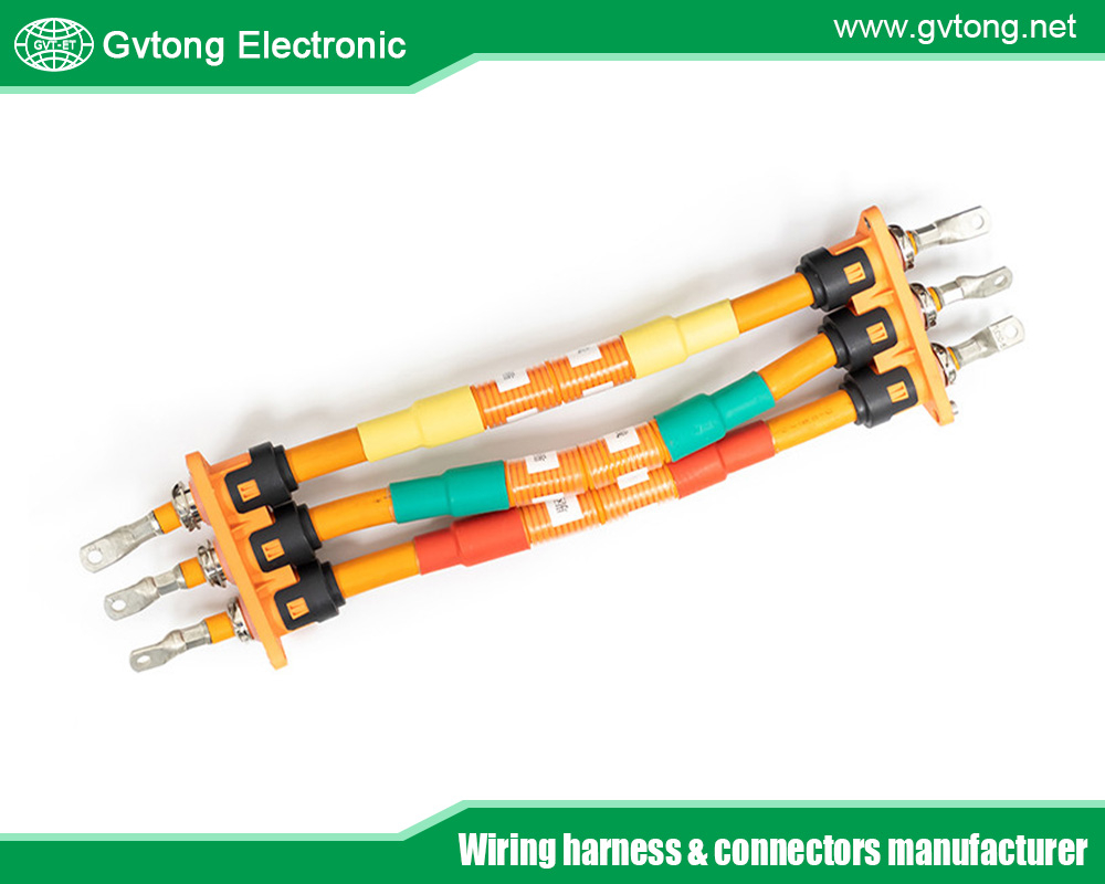
- Battery Pack Connectors: Often large, hard-shell “box” connectors with multiple power poles, low-voltage signals, and cooling interfaces. May be serviceable or laser-welded for life.
- Inverter/Motor Connections: Subject to extreme vibration and heat. Feature very high cyclic durability and robust locking.
- Charging Port/Inlet: The vehicle’s interface to the external world. Must withstand thousands of public charging cycles, abuse, and environmental exposure. Includes communication pins (CC, CP) for PLC (Power Line Communication) or CAN-based charging protocols.
- Service Disconnects: Manual connectors that allow technicians to physically segment the HV system for safe servicing. Often incorporate a visible air gap and may have an integrated fuse.
Future Trends and Challenges
The evolution of HV connectors is driven by the demands of next-generation EVs:
- Higher Voltages (900V to 1000V+): Enabling faster charging (e.g., 350 kW+). This requires enhanced dielectric materials, larger creepage/clearance, and advanced arc mitigation strategies.
- Increased Power Density: Connectors must carry more current in the same or smaller space, pushing thermal management to its limits.
- Integration & Modularity: Connectors are evolving into “smart modules” that integrate current sensors, temperature monitoring, and connectivity for predictive health monitoring.
- Automated Assembly: As production volumes soar, designs are adapting for fully automated mating and harnessing processes in the factory.
- Material Innovation: Development of new, higher-performance, and more sustainable plastics and elastomers.
Conclusion
The humble high-voltage connector is a cornerstone of electric vehicle safety and performance. It is a meticulously engineered system where electrical engineering, materials science, mechanical design, and safety logic converge. From its fail-safe HVIL circuit and robust metallic contacts to its environmental seals and EMI shield, every element works in harmony to ensure that the formidable power flowing through an EV’s veins is contained, controlled, and reliably delivered. As vehicles become more electric, connected, and automated, the role of these critical components will only grow in importance, continuing to enable the silent, powerful, and safe mobility of the future.
For more about how does a high-voltage connector in an automotive application work, you can pay a visit to Gvtong at https://www.gvtong.net/ for more info.
-

GH Series – DCDC Through-Wall Terminal Block – With Protective Cover
-

GVPT 3-core wiring connector
-

GB Series-Energy Storage Connector-10.0mm
-

GE Series-39-core rectangular connector-socket
-

GT Series-2-core/3-core Signal Connector
-

Photovoltaic Connector-Board Socket
-

Automotive FAKRA Connector – Board End, DC to 3GHz From RF Connectors And Cables Manufacturer In China
-

GH800 Series-2-core plastic high voltage connector