Blogs & News
We are focus on automotive wiring harness & connectors technology.
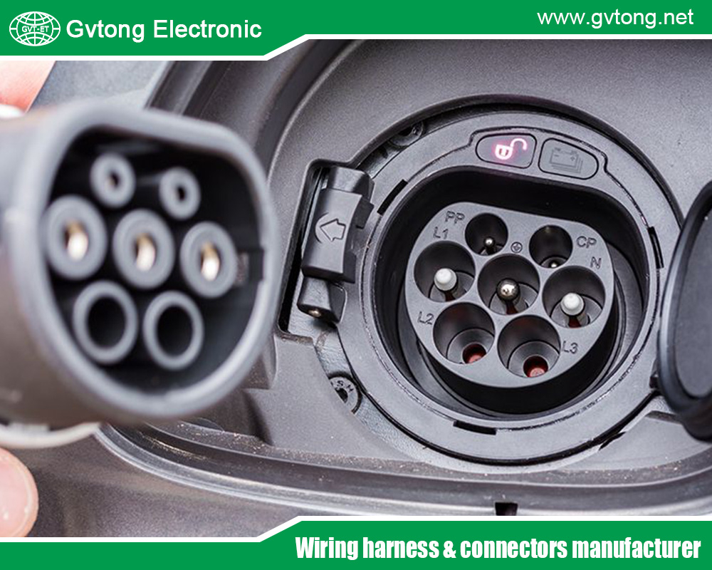
How to diagnose and exclude automotive Signal Connector to ensure their proper operation?
- Gvtong Electronic
- 2 Pin Way Car Waterproof Electrical Connector, 4 Pin Connector, auto Connector, Automobile Waterproof Connector, automotive electrical connector, Automotive electrical connectors, automotive Signal Connector, automotive Signal Connector company, automotive Signal Connector factory, automotive Signal Connector manufacturer, automotive Signal Connector supplier, automotive Vehicle Connector, Connecting Terminal, Copper Alloy Connector, durable Connectors, electrical battery connectors, electrical connector aviation connectors, electrical connectors, electrical wire connector, female electrical wire connector, high Current Connectors, high Voltage Interface Connectors, Latest Design Connectors, new Energy Connectors, plug Auto Electrical Wire Connectors, right Angle Pin Header Pcb Connector, Waterproof Connector, wire connectors electrical
- No Comments
Diagnosing and excluding automotive signal connectors to ensure proper operation involves a systematic approach to identify faults, verify functionality, and rule out issues. Signal connectors, critical for transmitting data in systems like sensors, infotainment, or engine control units, require careful inspection due to their role in maintaining reliable communication.
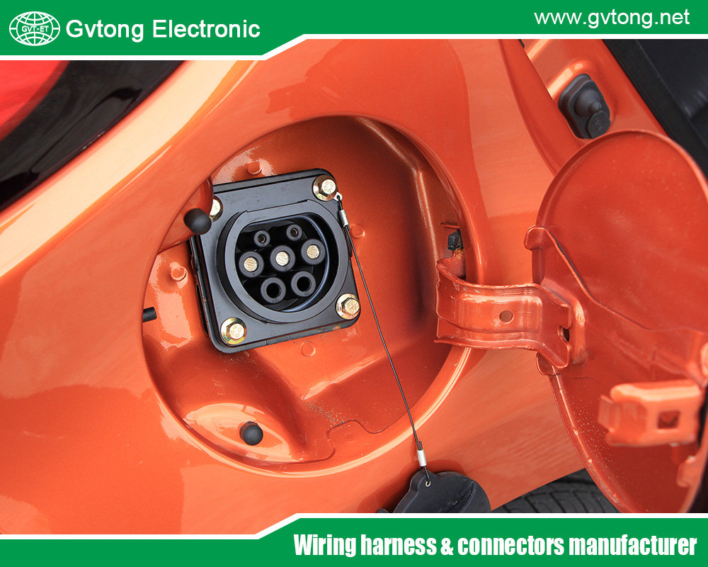
Below is a comprehensive guide based on industry insights, outlining steps to diagnose issues and confirm proper operation, ensuring the process is thorough yet accessible.
Research suggests that diagnosing signal connectors involves visual inspections, electrical testing, and environmental checks.
It seems likely that common issues include corrosion, loose connections, or damaged pins, which can disrupt signal integrity.
The evidence leans toward using tools like multimeters and diagnostic scanners to verify functionality and exclude faulty connectors.
Standards like ISO 10487 and SAE USCAR2 guide testing for reliability.
Step-by-Step Diagnosis and Exclusion Process
Visual Inspection
Purpose: Identify physical damage or environmental factors affecting the connector.
Steps:
Check for Physical Damage: Inspect the connector housing, pins, and terminals for bent pins, cracks, or deformation. For example, damaged pins can cause intermittent signals.
Examine for Corrosion or Contamination: Look for signs of oil, water, or dirt ingress, which can compromise signal integrity. Corrosion is a common issue in connectors exposed to moisture or chemicals.
Verify Locking Mechanism: Ensure the connector’s locking mechanism is secure, as loose connections can lead to signal loss.
Exclusion: If no physical damage, corrosion, or loose connections are found, the connector’s physical condition is likely not the issue. Proceed to electrical testing.
Electrical Testing with a Multimeter
Purpose: Verify electrical continuity and signal integrity.
Tools Needed: Digital multimeter, wiring diagram for the vehicle.
Steps:
Check Continuity: Set the multimeter to continuity mode and test each pin pair to ensure there are no open circuits. A lack of continuity indicates a broken or disconnected wire.
Measure Resistance: Check for high resistance in the connector, which could indicate corrosion or poor contact. Resistance should be low (typically <1 ohm) for signal connectors Automotive Electrical Connectors.
Test for Short Circuits: Use the multimeter to check for unintended connections between pins or to ground, which could cause signal interference.
Exclusion: If continuity is intact, resistance is low, and no shorts are detected, the connector’s electrical pathway is likely functional. Move to signal-specific testing.
Signal Integrity Testing
Purpose: Ensure the connector transmits data accurately, critical for systems like CAN bus or sensor networks.
Tools Needed: Diagnostic scanner (e.g., OBD-II scanner), oscilloscope (for advanced diagnostics).
Steps:
Use a Diagnostic Scanner: Connect an OBD-II scanner to check for error codes related to the system the connector serves (e.g., sensor or communication faults). Codes like P0700 (transmission control) or U0100 (lost communication with ECM) may indicate connector issues.
Oscilloscope Testing (Optional): For high-speed data systems like CAN bus, use an oscilloscope to verify signal waveforms. Distorted or noisy signals suggest connector issues, such as high contact resistance or poor shielding.
Exclusion: If no error codes are present and signals are clean, the connector is likely transmitting data correctly. Proceed to environmental testing.
Environmental and Stress Testing
Purpose: Confirm the connector’s performance under real-world conditions, such as vibration or temperature extremes.
Steps:
Check Seals and IP Rating: Verify that seals (e.g., fluorosilicone or EPDM) are intact to prevent oil or moisture ingress, critical for oil-resistant connectors. A compromised seal can lead to intermittent failures.
Vibration Testing: Manually shake or tap the connector while monitoring with a multimeter or scanner to detect intermittent connections caused by loose pins or poor locking mechanisms.
Temperature Check: If possible, test the connector in operating conditions (e.g., engine bay heat) to ensure it maintains performance, as materials like PBT or PA66 are designed for high temperatures.
Exclusion: If the connector withstands environmental stresses without issues, it is likely reliable under operational conditions.
Functional Testing in the System
Purpose: Verify the connector’s performance within the vehicle’s system.
Steps:
Reconnect and Test System: After confirming physical and electrical integrity, reconnect the connector and test the associated system (e.g., sensor output, audio system, or CAN bus communication). For example, ISO 10487-compliant connectors for car audio should produce clear sound without interference.
Monitor for Intermittency: Operate the vehicle under normal conditions to check for intermittent faults, which may indicate a subtle connector issue.
Exclusion: If the system functions correctly with no errors or intermittency, the connector is likely operating properly.
Compare with Replacement or Known Good Connector
Purpose: Rule out the connector as the fault source by substitution.
Steps:
Swap with a Known Good Connector: If issues persist after testing, replace the connector with a new or verified one of the same type (e.g., matching pin count and specifications).
Retest the System: If the system works with the new connector, the original was faulty. If issues persist, the problem lies elsewhere (e.g., wiring or ECU).
Exclusion: A functioning system with a replacement connector confirms the original as the issue, while continued issues exclude the connector.
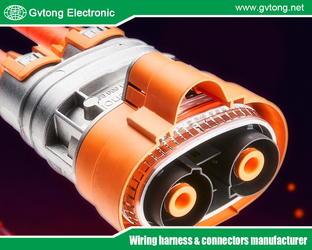
Common Issues and Symptoms
Corrosion: Causes high resistance or signal loss, often visible as green or white deposits.
Loose Connections: Leads to intermittent signals, detectable during vibration testing.
Damaged Pins: Results in open circuits or poor contact, identified during visual inspection.
Oil/Moisture Ingress: Compromises insulation, causing shorts or signal noise, often due to failed seals.
Tools and Resources
Multimeter: For continuity, resistance, and short-circuit tests.
OBD-II Scanner: To check for system error codes.
Oscilloscope: For advanced signal analysis (optional).
Wiring Diagram: Essential for identifying correct pins and circuits, available in the vehicle’s service manual.
Manufacturer Datasheets: Provide specifications for connector testing.
Standards Compliance
Testing should align with standards like:
SAE USCAR2: Specifies performance tests, including vibration and fluid immersion, to ensure reliability Automotive Electrical Connectors | Arrow.com.
ISO 10487: Defines pin assignments for audio connectors, aiding in correct testing ISO 10487.
Practical Considerations
Safety First: Disconnect the vehicle’s battery before testing to avoid electrical shock or damage.
Consult the Manual: Use the vehicle’s service manual to locate connectors and understand system requirements.
Professional Help: If unsure, consult a qualified mechanic or use resources.
Clean Connectors: If corrosion is minor, clean with contact cleaner and a brush, then retest.
For more about How to diagnose and exclude automotive Signal Connector to ensure their proper operation? you can pay a visit to Gvtong at https://www.gvtong.net/signal/ for more info.
Recent Posts
How to Diagnose and Repair Automotive Signal Connector Failures
How to Install and Maintain Low Pressure Automotive Connectors
Heat Shrink vs. Crimp: Choosing the Right 12V Car Wire Connector
Best 12V Automotive Wire Connectors for Reliable Electrical Connections
Tags
Recommended Products
-
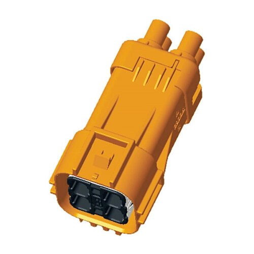
High voltage connector-GH630 series-4P
-
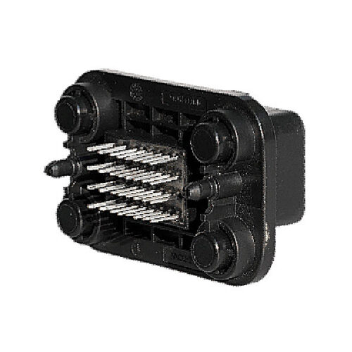
GE Series-32pin Signal Connector Right Angle Socket
-
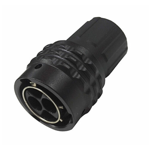
GR Series-2-core 12# circular signal connector
-
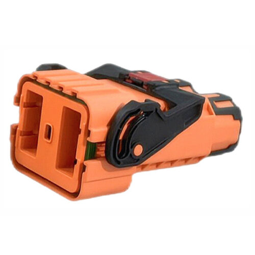
GH Series-HV6-2-core Plastic High Voltage Connector
-
Automotive Plastic Injection Parts
-
Copper bus fixing seat
-
DCDC wall-through terminal-double-headed thread
-
GH280 Series-2-core plastic high voltage connector
