Connector manufacturer
Connector manufacturer
How to Diagnose and Repair Automotive Signal Connector Failures
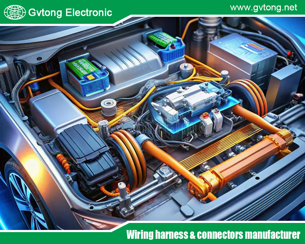
In the modern automobile, where the lines between mechanical machine and rolling computer have blurred, a single, seemingly insignificant component acts as the unsung hero of functionality: the electrical connector. While engineers and enthusiasts often focus on the brain (ECU) or the muscles (actuators, sensors), it is the nervous system—the wiring harness and its connectors—that enables communication. Signal connector failures are among the most prevalent, elusive, and frustrating issues in automotive diagnostics. They can manifest as intermittent glitches, complete system failures, or perplexing false codes, leading to misdiagnosis and wasted time and money. This technical guide provides a structured approach to diagnosing and repairing these critical yet vulnerable components.
The Critical Role of Signal Connectors
Unlike high-current power connectors designed to handle amps for starters and motors, automotive signal connectors are responsible for low-voltage, low-current communication. They carry data from sensors (oxygen sensors, crankshaft position sensors, wheel speed sensors) to control modules and deliver command signals from modules to actuators (solenoids, injectors, throttle bodies). A typical modern vehicle houses hundreds of these connectors, with some, like those for the CAN bus (Controller Area Network), handling thousands of messages per second. Their integrity is non-negotiable for accurate system operation.
Common Failure Modes and Their Root Causes
Understanding how automotive signal connectors fail is the first step in diagnosis. Failures are rarely catastrophic; they are often progressive and environment-driven.
-
Terminal Oxidation and Corrosion: The primary enemy. Moisture ingress, often due to damaged seals, condensation from temperature cycling, or exposure to road spray, leads to oxidation on the pin and socket surfaces. This creates a non-conductive layer or increases resistance, weakening or interrupting the signal. Green or white powdery deposits are a telltale sign.
-
Terminal Fretting Corrosion: A more subtle issue caused by micro-movement between mated terminals due to vibration or thermal expansion/contraction. This wears away the protective plating, exposing base metals to oxidation. The resultant oxide is abrasive, accelerating wear and increasing resistance. This is a classic cause of intermittent problems.
-
Terminal Relaxation and Poor Retention: The spring tension in the female terminal socket can degrade over time due to thermal cycling or repeated mating cycles. A loose connection results in high resistance and intermittent contact. Similarly, the primary locking mechanism (the connector housing clip) and the secondary terminal position assurance (TPA) lock can break or disengage, allowing terminals to back out.
-
Pin/Bent or Damaged Terminals: Forced mis-mating, using incorrect tools, or debris intrusion can physically bend or break the delicate pins. A single bent pin can disable an entire system.
-
Wire Fatigue and Crimp Failure: The point where the wire is crimped to the terminal is a high-stress area. Vibration can cause the wire to fatigue and break, often inside the insulation where it’s not visible (“green wire” break). A poor initial crimp can also lead to high resistance and eventual failure.
-
Connector Housing Damage: Physical impact, UV degradation, or chemical exposure can crack or distort the connector housing. This compromises the environmental seal and can misalign terminals.
Structured Diagnostic Approach
A haphazard approach leads to confusion. Follow this systematic process.
Phase 1: Preliminary Investigation
-
Symptom Analysis: Is the failure constant or intermittent? Does it correlate with temperature (cold/hot), humidity, or specific vehicle maneuvers (turning, braking)? Intermittency often points to connectors.
-
Scan Tool Interrogation: Use a quality OBD-II scanner or manufacturer-specific tool. Look for codes related to sensor plausibility, signal implausibility, open circuits, or short to ground. Note which modules are communicating and if any are offline.
-
Visual Inspection: This is 80% of the diagnosis. Look for obvious damage, cracked housings, missing seals, or corrosion around the connector body. Check for chafing on the wiring harness near anchor points.
Phase 2: Physical and Electrical Testing (Vehicle OFF)
-
Disconnect Safely: Always disconnect the battery before unplugging connectors for inspection, especially airbag and powertrain-related ones.
-
Internal Inspection: Carefully separate the connector. Inspect for:
-
Moisture/Contaminants: Look for water, dirt, or dielectric grease (sometimes over-applied).
-
Terminal Condition: Examine pins and sockets for corrosion, discoloration, bending, or burning.
-
Seal Integrity: Each wire should have a sealing grommet in place. The connector housing may have a main seal.
-
Locking Mechanisms: Ensure the TPA and connector latch are intact and engaged.
-
-
Terminal Testing:
-
Back-pin Probing: This is the gold standard. Use specialized male and female test probes that fit into the connector from the wire side alongside the terminal, maintaining the circuit. Do not forcibly insert probes into the mating face of sockets, as this will damage them.
-
Resistance Check: Measure the resistance of the circuit through the connector. Compare to specifications (often less than 1-2 Ohms for a good connection). Wiggle the connector and harness while measuring to detect intermittency.
-
Pull Test: Gently tug on each wire at the connector back. It should not pull out. A proper crimp holds firm.
-
Phase 3: Dynamic Testing (Vehicle ON/Running)
-
Voltage and Signal Analysis: With the system powered and the connector properly mated (using back-pin probes), use a digital multimeter (DMM) or oscilloscope.
-
Reference Voltage (5V): Check sensor supply voltages for drop across the connector.
-
Signal Integrity: For variable signals (like throttle position), observe for smooth transition or glitches as the component is actuated. An oscilloscope is invaluable here for viewing noise or signal dropout.
-
Voltage Drop Test: Perform a loaded voltage drop across the suspect connector. A drop of more than 0.1V under load indicates a problem.
-
Repair Techniques and Best Practices
Once the faulty connector or terminal is identified, proper repair is essential.
1. Terminal Repair:
-
De-pinning: This is the preferred method. Use manufacturer-specific de-pinning tools to safely release the terminal from the connector housing without damage. These tools are designed to disengage the terminal’s primary retention tang.
-
Cleaning: For minor corrosion, use electrical contact cleaner and a dedicated electronic contact brush. Never use abrasives like sandpaper or files, which remove protective plating.
-
Replacement: Always replace the affected terminal(s). Use high-quality, OEM-spec terminals and the correct crimping tool.
-
Crimping: A proper crimper dies a precise, F-shaped crimp that compresses the wire barrel onto the conductor and the insulation grip onto the insulation. Vise-grip or generic crimpers are unacceptable for signal wires.
2. Connector Housing/Seal Repair:
-
Replace the entire connector housing if cracked, melted, or if seals are degraded.
-
Ensure every wire seal is present and correctly seated on the wire before inserting the terminal into the new housing.
-
Apply dielectric grease sparingly. Its purpose is to exclude moisture and prevent future corrosion, not to conduct electricity. Use only on the terminal mating surfaces after crimping.
3. Wire Repair:
-
For damaged wires, use solder and heat-shrink tubing with adhesive lining, or use OEM-approved splice kits with ultrasonic welding or qualified crimp splices.
-
Never use “butt connectors” without proper sealing for under-hood or exterior applications.
-
Route the repaired harness correctly, using existing clips and away from heat/vibration sources.
Preventive Measures
-
Seal Re-assembly: During any repair, ensure all connector seals are clean and fully seated.
-
Protection: Use harness wrap or conduit in high-heat or high-abrasion areas.
-
Careful Handling: Never pull on wires to disconnect a connector. Use the locking tab. Avoid forcing connectors together.
Case Study: Intermittent Misfire on Cylinder 3
-
Symptom: P0303 code, misfire only when humid or under heavy load.
-
Diagnosis: Visual inspection reveals the ignition coil connector for cylinder 3 has a slightly cracked housing. No visible corrosion inside. Back-pin probing at the coil shows 12V supply and ground are good. Signal from ECU is intermittent when the harness is wiggled.
-
Repair: De-pin the signal wire terminal from both the engine harness connector and the coil connector. Inspection reveals fretting corrosion on the female socket. Both terminals are replaced, and the cracked coil connector housing is replaced.
-
Verification: Wiggle test confirms solid connection. Code cleared, and long-term test shows no misfire return.
Conclusion
Diagnosing and repairing automotive signal connector failures demands a shift from component-swapping to systematic detective work. The investment in proper tools—back-pin probes, quality DMM, de-pinning tools, and a correct crimper—pays for itself in diagnostic accuracy and repair durability. By understanding the failure modes, methodically testing, and executing repairs to OEM standards, technicians can solve some of the most stubborn problems in modern vehicles. In an era of increasing electronic complexity, mastering the humble connector is not just a skill—it is a necessity for ensuring vehicle reliability and performance. Remember: the signal must flow, and its path is only as good as the connections it travels through.
For more about how to diagnose and repair automotive signal connector failures, you can pay a visit to Gvtong at https://www.gvtong.net/ for more info.
-

Automotive FAKRA Connector – Board End, DC to 3GHz From RF Connectors And Cables Manufacturer In China
-

GE Series-39-core rectangular connector-socket
-

GE Series-10PIN Right Angle Connector Socket
-

Copper bus fixing seat
-

Pin header and female header
-
")
Signal connector – waterproof, three rows, 35 cores
-

Photovoltaic Connector-Line End Socket
-

DCDC wall-through terminal – with protective cover