Blogs & News
We are focus on automotive wiring harness & connectors technology.
Testing Methods and Evaluation Means for 4-Cavity Connectors
- Gvtong Electronic
- 4-cavity connectors, ADAS sensor connectors, automotive electrical connector, automotive High voltage connector, automotive Low voltage connector, automotive Oil-resistant Connectors, automotive Signal Connector, automotive waterproof connectors, Battery management system (BMS) connectors, best 4-cavity connectors China, best photovoltaic connectors for solar panels, Best Photovoltaic Solar Battery Connectors For Energy Storage Systems, China Energy Storage Connector Manufacturers, China High Current Connectors Manufacturer, china photovoltaic connectors manufacturers, electric vehicle EV connector supplier, EV charging connectors, EV charging connectors manufacturers, Fuel cell connectors, In-cabin infotainment connectors, Lightweight automotive connectors, Modular automotive connectors, OEM-specific connectors, Pre-charge/discharge connectors, Quick-fit automotive connectors, Recyclable material connectors, Redundant safety connectors, V2X communication connectors, Wireless charging connectors
- No Comments
Testing Methods and Evaluation Means for 4-Cavity Connectors
In modern electronic devices, connectors serve as critical components for establishing electrical connections and signal transmission, with their performance directly impacting the reliability and stability of the entire system. Thanks to their unique structural design, 4-cavity connectors can simultaneously transmit multiple signals or power supplies, finding wide applications in fields such as aerospace, communications, and automotive electronics. To ensure that 4-cavity connectors operate normally in various complex environments, comprehensive and accurate testing and evaluation are essential. This article details the testing methods and evaluation means for 4-cavity connectors, covering electrical performance, mechanical performance, environmental adaptability, and reliability.
Electrical Performance Testing
1. Contact Resistance Test
Contact resistance is a key indicator for measuring the electrical performance of 4-cavity connectors, directly influencing signal transmission quality and stability. It is defined as the resistance generated when current passes through the contact points of the connector during normal operation. Excessive contact resistance can lead to signal attenuation, heat generation, or even transmission interruption.The four-wire method (also known as the Kelvin test method) is commonly used for testing. This method employs two independent sets of wires: one for providing a constant current and the other for measuring the voltage drop across the connector. Since the voltage measurement wires carry almost no current, this method eliminates the influence of measurement lead resistance on the result, yielding a more accurate contact resistance value. During testing, the test current should be set to the rated operating current of the connector or slightly higher to simulate real-world operating conditions. Additionally, it is crucial to ensure the accuracy and stability of the testing equipment and calibrate it regularly.
2. Insulation Resistance Test
Insulation resistance refers to the resistance between conductors in a connector during normal operation, relating to the connector’s safety and reliability. Low insulation resistance may cause faults such as leakage or short circuits, endangering equipment and personnel.High-voltage testing is typically used, where an insulation resistance tester applies a specific DC voltage to the insulating parts of the connector and measures the leakage current through the insulating material. Insulation resistance is then calculated using Ohm’s law. The selection of test voltage should be based on the connector’s operating voltage and the characteristics of the insulating material, generally several times the operating voltage. For example, a connector with a 50V operating voltage may use a test voltage of 500V or 1000V. Before testing, ensure the connector surface is clean and dry to avoid affecting results due to surface contamination or moisture.
3. Withstand Voltage Test
The withstand voltage test (also known as the dielectric strength test) evaluates the maximum voltage a 4-cavity connector can withstand within a specified time to check if its insulation performance meets requirements.The test method typically involves gradually increasing the voltage. A withstand voltage tester applies AC or DC high voltage between the connector’s conductors or between conductors and the housing, then raises the voltage at a constant rate until reaching the specified test voltage, which is maintained for a certain period (e.g., 1 minute). During testing, closely monitor the connector for breakdown, flashover, or leakage. If any of these occur, the connector’s insulation performance is deemed unqualified. Note that test voltage application must comply with relevant standards and specifications to avoid irreversible damage to the connector from excessively high voltages.
4. Current Carrying Capacity Test
Current carrying capacity refers to the maximum current a 4-cavity connector can withstand during normal operation, determining its power transmission capability in practical applications.The test method usually involves gradually increasing the current. A DC or AC power supply delivers current to the connector, while a temperature sensor monitors temperature changes. As the current increases, the connector’s temperature rises. When the temperature stabilizes, record the current value, which represents the connector’s current carrying capacity under the given heat dissipation conditions. During testing, ensure the connector’s heat dissipation conditions match the actual usage environment, using natural cooling or forced air cooling as needed. Additionally, monitor the temperature rise rate to prevent excessive current from causing rapid temperature increases and damaging the connector.
5. Signal Integrity Test
With the development of electronic devices toward high speed and high frequency, signal integrity issues have become increasingly prominent. For 4-cavity connectors, signal integrity testing mainly includes transmission delay testing, crosstalk testing, and return loss testing.
- Transmission Delay Test: Measures the delay time of signals as they pass through the connector, reflecting signal transmission speed. High-speed oscilloscopes are typically used to measure the transmission time from the input to the output port. During testing, a high-speed signal source inputs standard pulse or sine wave signals, and the test equipment’s bandwidth must meet requirements.
- Crosstalk Test: Evaluates the interference between adjacent signal lines during signal transmission, affecting signal accuracy and reliability. Network analyzers are used to measure the coupling coefficient between adjacent signal lines. A test signal is input into one signal line, and the interference signal intensity coupled to adjacent lines is measured to calculate the crosstalk value.
- Return Loss Test: Measures the loss of signal reflection during transmission, reflecting the matching performance between the connector and the transmission line. Network analyzers are also used to measure the signal reflection coefficient. A larger return loss value indicates less signal reflection and better matching; a smaller value indicates more reflection and poorer matching.
Mechanical Performance Testing
1. Insertion and Extraction Force Test
Insertion and extraction forces refer to the forces required to insert and remove a 4-cavity connector during normal operation. Appropriate forces ensure both secure connections and easy operation. Excessive force may damage the connector or make operation difficult, while insufficient force may cause poor contact.Dedicated insertion and extraction force testers are used, which measure force changes during the process via high-precision force sensors and display/record data in real time. During testing, the connector is fully mated or removed at a specified speed, and the maximum and minimum insertion/extraction forces are recorded and compared with product specifications. Ensure the test direction and angle match actual usage to guarantee result accuracy.
2. Insertion and Extraction Life Test
Insertion and extraction life is a key indicator of a 4-cavity connector’s mechanical durability, reflecting its ability to withstand repeated plugging and unplugging over time.Automated insertion/extraction test equipment is used to simulate real-world operations, with parameters such as speed,cycles, and stroke set in advance. The connector is fixed on the equipment and subjected to repeated plugging/unplugging until the specified cycle count is reached. During the process, periodically test electrical performance (e.g., contact resistance, insulation resistance) to assess performance changes. The connector is considered to have reached its service life when electrical performance deteriorates or insertion/extraction forces exceed specified limits.
3. Vibration Test
Vibration testing evaluates the vibration amplitude and frequency a 4-cavity connector can withstand during normal operation to check its reliability in vibrating environments. In practice, connectors may be subjected to vibrations from equipment or external sources (e.g., vehicle engines, aircraft flight).Vibration tables are used to mount the connector and apply vibration tests with specified frequency, amplitude, and direction. Vibration types include sinusoidal vibration (simulating periodic environments) and random vibration (simulating complex real-world conditions). During testing, monitor electrical performance (e.g., contact resistance, insulation resistance) in real time to ensure stable connections. Electrical faults (e.g., poor contact, short circuits) indicate unqualified vibration resistance.
4. Shock Test
Shock testing evaluates the impact force a 4-cavity connector can withstand during normal operation to check the structural integrity and electrical stability under sudden impacts (e.g., collisions, drops).Shock testing machines are used to apply specified impact loads by controlling parameters such as shock pulse waveform (e.g., half-sine, square), peak acceleration, and pulse duration. During testing, monitor electrical performance in real time and inspect the connector’s appearance and structure for damage. Abnormal electrical performance or structural damage after shock indicates unqualified shock resistance.
Environmental Adaptability Testing
1. Temperature Cycle Test
Temperature cycle testing evaluates a 4-cavity connector’s ability to withstand temperature changes within a specified range, checking performance stability in different thermal environments (e.g., rapid temperature shifts from outdoor cold to indoor warmth or device heating/cooling cycles).Temperature cycle chambers are used to subject the connector to predefined temperature profiles, typically including high-temperature, low-temperature, and transition phases (e.g., cycling from -40°C to 85°C and back, holding at each extreme for a set time). Electrical performance is tested at each temperature stage and during transitions to ensure normal operation across temperature ranges.
2. Damp Heat Test
Damp heat testing evaluates a 4-cavity connector’s resistance to humid and hot environments, checking its anti-moisture and anti-corrosion capabilities. In humid conditions, moisture may penetrate the connector, reducing insulation and corroding metal parts.Damp heat chambers are used to set specified temperature and relative humidity (e.g., 40°C, 95% RH) for a duration (e.g., 48-96 hours). During testing, periodically measure electrical performance (insulation resistance, contact resistance) and inspect for corrosion or rust. Deteriorated electrical performance or visible damage indicates unqualified damp heat resistance.
3. Salt Spray Test
Salt spray testing evaluates a 4-cavity connector’s corrosion resistance in salt-laden environments (e.g., marine or industrial settings), where salt mist can degrade metal components and affect performance.Salt spray chambers are used to expose the connector to a specified salt mist concentration (e.g., 5% NaCl solution) for a set duration. Test types include neutral, acidic, and copper-accelerated salt spray tests, selected based on usage conditions. After testing, the connector is cleaned and dried, then tested for electrical performance and visual corrosion. Corrosion marks or poor contact indicate unqualified salt spray resistance.
4. Low Pressure Test
Low pressure testing evaluates a 4-cavity connector’s ability to withstand air pressure changes in low-pressure environments (e.g., high altitudes in aerospace applications).Low pressure chambers are used to gradually reduce internal pressure to a specified level (simulating high-altitude conditions) and hold it for a period. During testing, monitor electrical and mechanical performance for issues like arcing, air leakage, or structural deformation. Abnormalities indicate unsuitability for low-pressure environments.
Reliability Testing
1. Durability Test
Durability testing assesses a 4-cavity connector’s long-term reliability by simulating real-world operating conditions (e.g., plugging/unplugging, electrical loading, temperature changes) to monitor performance changes over time.Composite testing methods are used, such as combining insertion/extraction life tests with rated electrical loads and temperature cycles to accelerate aging. Regularly test performance metrics (electrical, mechanical, appearance) during testing. When metrics degrade significantly or exceed allowable limits, record the test time and cycles to evaluate durability.
2. Accelerated Aging Test
Accelerated aging testing evaluates long-term reliability by subjecting connectors to harsher conditions than normal use (e.g., higher temperatures, humidity, or voltage) to speed up material aging and performance degradation.For example, in high-temperature/high-humidity accelerated aging, connectors are placed in an 85°C/85% RH environment with electrical loads for 1,000-2,000 hours, after which performance is tested. Compared to normal testing, accelerated aging provides faster insights into long-term performance trends, supporting design improvements and quality evaluations.
Appearance and Dimensional Inspection
1. Visual Inspection
Visual inspection is a preliminary quality assessment method using direct observation or magnification (e.g., magnifying glasses) to check for surface defects (cracks, deformation, material shortages, oxidation, coating peeling) in connectors. These defects may affect mechanical, electrical, and reliability performance.Inspect all components (housing, pins, insulators) for smooth, flawless surfaces. Verify clear and complete markings (model, specifications, manufacturer, date).
2. Dimensional Measurement
Dimensional measurement ensures connector dimensions comply with design and standards, critical for proper mating and installation with other components.High-precision tools (calipers, micrometers, projectors, CMMs) measure key dimensions (pin spacing, pin length, housing size). Follow strict measurement standards and procedures to ensure accuracy. Compare results with design drawings and specifications; deviations beyond allowable limits may cause assembly issues.
Comprehensive Evaluation and Conclusion
Through the above electrical, mechanical, environmental, reliability, and dimensional tests, a comprehensive assessment of 4-cavity connector performance and quality can be conducted. Compare test results with relevant standards, specifications, and design requirements to determine fitness for use.If a connector passes all tests and meets all indicators, it is deemed reliable for stable operation in target environments. If failures occur in any test, analyze and address root causes (design flaws, material issues, process defects) through optimizations (redesign, material replacement, process improvements). Retest modified connectors until all indicators are satisfied.In summary, scientific and rigorous testing and evaluation are essential for ensuring 4-cavity connector performance and quality. They provide technical support for design, production, and application, driving industry development and meeting the demand for high-performance, reliable connectors in modern electronics.
For more about the best testing methods and evaluation means for 4-cavity connectors, you can pay a visit to Gvtong at https://www.gvtong.net/ for more info.
Recent Posts
How to Diagnose and Repair Automotive Signal Connector Failures
How to Install and Maintain Low Pressure Automotive Connectors
Heat Shrink vs. Crimp: Choosing the Right 12V Car Wire Connector
Best 12V Automotive Wire Connectors for Reliable Electrical Connections
Tags
Recommended Products
-
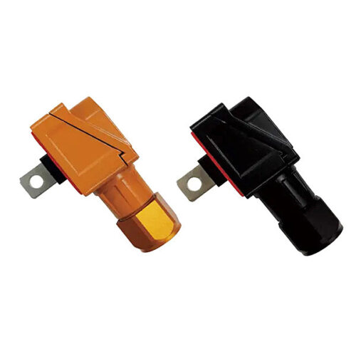
Positive and negative terminal box – oblique opening
-
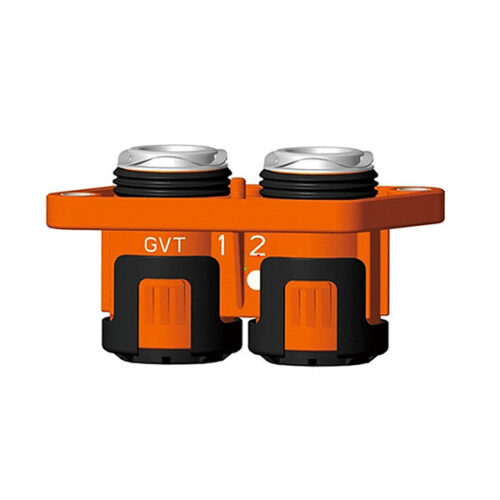
GIPT two-core wiring connector
-
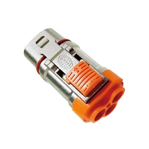
Metal connector-3.6mm-3 core
-
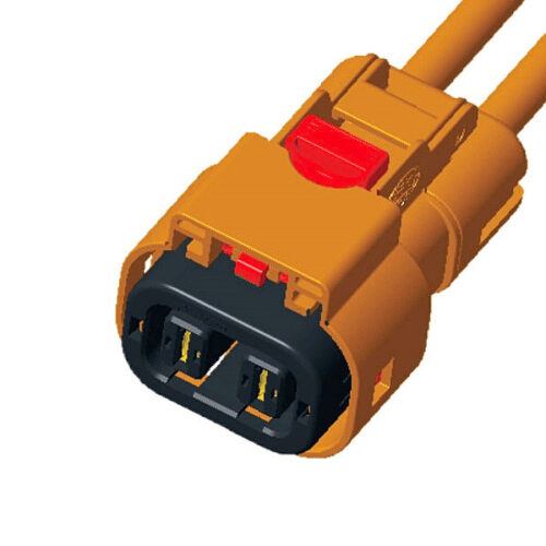
Connector plug+socket-GH630 series-2P
-
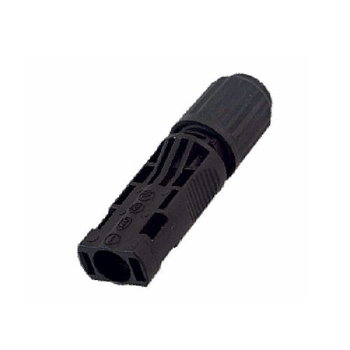
Photovoltaic connector – Wire end socket
-
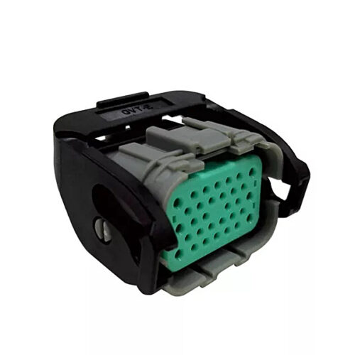
Rectangular connector-32 core
-
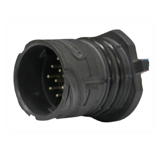
GE Series-16-core cylinder connector
-
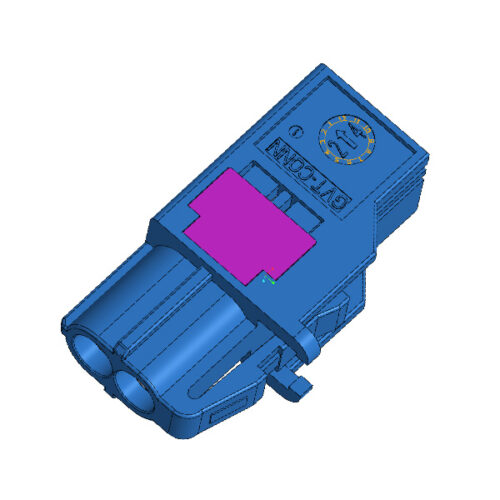
Automotive MINI Fakra High-Speed 2Pin Female To Fakra Male Z Code Connector

