Connector manufacturer
Connector manufacturer
To Avoid Overheating Failure, What Should be Considered in the Design of Automotive High-Current Connectors?
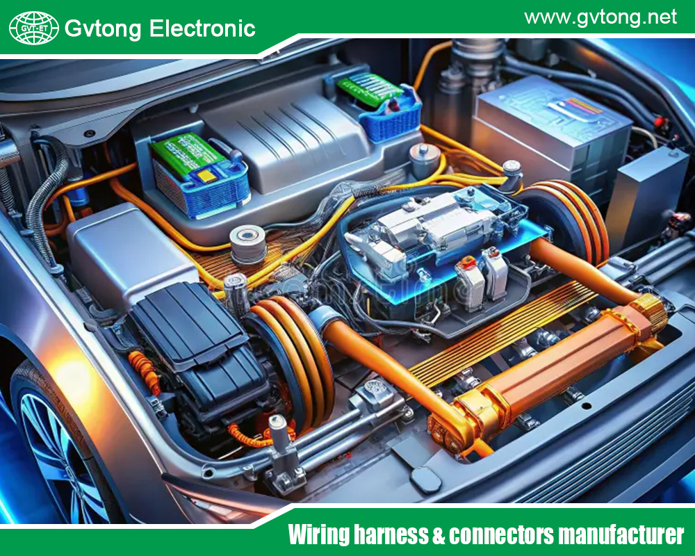
In the automotive industry, particularly with the surge in electric vehicles (EVs) and hybrid systems, high current connectors play a pivotal role in ensuring efficient power transmission. These connectors handle currents often exceeding 100A, and in fast-charging scenarios, up to 500A or more, at voltages ranging from 400V to 1000V. However, one of the most critical challenges in their design is managing contact resistance—the electrical resistance at the interface where two conductive surfaces meet. Excessive contact resistance leads to Joule heating, where power loss (P = I²R) manifests as heat, potentially causing overheating failures. Such failures can result in melted insulation, degraded performance, arcing, or even fires, compromising vehicle safety and reliability.
To mitigate these risks, designers must focus on controlling contact resistance below specific threshold values. Industry standards, such as those from the United States Council for Automotive Research (USCAR), provide guidelines on acceptable limits. For instance, USCAR-2 specifies maximum total connection resistance values depending on terminal size, with larger terminals for high current applications limited to 1 mΩ or less. Overheating is typically defined as a temperature rise exceeding 55°C above ambient, a threshold that triggers thermal degradation. Accurate measurement of contact resistance is equally vital, employing methods like the Kelvin four-wire technique to eliminate measurement errors and ensure precise readings.
This article explores the threshold values for contact resistance that must be controlled to prevent overheating in automotive high current connectors. It also examines common test methods for measuring this resistance accurately. By drawing on standards like USCAR-2, SAE specifications, and practical examples from EV applications, we highlight how these elements contribute to robust connector designs. As the automotive sector shifts toward electrification, understanding these aspects is essential for engineers, manufacturers, and regulators to advance safe, efficient mobility solutions.
Overview of Overheating Failures in Automotive High Current Connectors
Overheating in automotive high current connectors arises primarily from elevated contact resistance, which converts electrical energy into unwanted heat. In EVs, where batteries deliver high power to motors and charging systems, connectors are subjected to intense thermal stresses. For example, during fast charging, currents can spike, amplifying heat generation if resistance is not minimized. Common failure modes include thermal runaway, where heat softens materials, increases resistance further, and creates a vicious cycle leading to connector ablation or vehicle fires.
Contact resistance comprises constriction resistance (due to limited contact points) and film resistance (from oxides or contaminants). In high current scenarios, even minor increases—say from 0.2 mΩ to 1 mΩ—can produce significant heat. Consider a 400A current: at 1 mΩ, power loss is 160W, potentially raising temperatures by over 30°C, affecting mechanical tolerances and insulation integrity. In contrast, designs with <50 µΩ (0.05 mΩ) resistance reduce this to negligible levels, preventing overheating. Environmental factors exacerbate the issue. Automotive connectors operate in temperatures from -40°C to +125°C, with vibrations causing fretting corrosion that elevates resistance over time. Standards like USCAR-2 address this by requiring stable resistance after durability tests, such as current cycling (45 minutes on, 15 minutes off for 1000 hours), where temperature rise must not exceed 55°C. High current connectors, like those in battery packs or inverters, use materials such as silver-plated copper to achieve low resistance, but poor crimping or mating can undermine this.
Overheating not only reduces efficiency—wasting battery energy—but also poses safety risks. Reports from EV charging stations show handles overheating due to rising resistance, leading to power derating or shutdowns. To avoid such failures, designers incorporate features like multi-point contacts or larger surface areas to distribute current evenly. Understanding the interplay between resistance, current, and heat is crucial, as it informs threshold setting and testing protocols in the design phase.
Threshold Values for Contact Resistance to Avoid Overheating
The threshold value for contact resistance in automotive high current connectors is the maximum allowable resistance that prevents excessive temperature rise, typically defined as <55°C above ambient to avoid material degradation. Industry consensus, per USCAR-2, sets initial total connection resistance limits based on terminal size: for large 9.5mm terminals handling high currents, it’s ≤1 mΩ, while smaller terminals may allow up to 25 mΩ. After durability testing, resistance should not exceed twice the initial value or specific post-test limits, such as 6 mΩ for certain outer contacts.
In EV high current applications, thresholds are stricter to handle peaks. For instance, connectors like Molex’s COEUR series achieve 0.1-0.4 mΩ, supporting 75-350A without significant heating. A key guideline is maintaining resistance low enough so that voltage drop remains <50 mV at rated current, equating to <1 mΩ for many systems (since 1 mΩ = 1 mV/A). Exceeding this can lead to overheating; for 400A, 1 mΩ generates 160W of heat, while <0.05 mΩ limits it to <8W.
Thresholds vary by application. In charging connectors, resistance <0.5 mΩ is targeted to prevent handles from becoming “uncomfortably hot” at moderate loads. Standards like SAE J1772 for EV charging imply similar limits through temperature rise tests. Designers use derating curves to determine safe currents, ensuring resistance doesn’t cause >50°C rise in operational environments.
To control resistance, focus on forward force (F), where R ∝ 1/F², per formulas in terminal analysis. Surface treatments reduce film resistance, and multi-lamella designs increase contact points. In practice, thresholds are validated through maximum current capability tests, stopping when rise exceeds 55°C. For bolted connections in high current busbars, <10 µΩ is ideal, but automotive plug-ins aim for 0.2-1 mΩ.
Ultimately, the threshold is context-specific but generally <1-5 mΩ initial for high current, with monitoring for increases >50% indicating potential overheating risks.
Factors Influencing Contact Resistance and Overheating
Several factors influence contact resistance, directly impacting overheating risks. Material selection is paramount: copper alloys with silver plating minimize oxidation, keeping resistance low. However, fretting from vibrations can form insulating films, increasing resistance over time. Contact force affects the effective area; insufficient force leads to higher constriction resistance.
Environmental exposure—humidity, salt, and temperature cycles—accelerates degradation. In USCAR tests, post-humidity resistance must remain within thresholds. Current density is critical: high currents amplify I²R losses, so larger terminals reduce density.
Design features like error-proofing and sealing prevent contaminants, while thermal management (e.g., cooling fins) dissipates heat. In EVs, resistance thresholds account for dynamic loads, with smart monitoring detecting rises early.(Word count: 1,378)
Common Test Methods for Accurately Measuring Contact Resistance
Accurate measurement of contact resistance is essential to validate thresholds and predict overheating. Common methods include the Kelvin four-wire technique, voltage drop test, and dry circuit resistance The Kelvin method uses separate current injection and voltage sensing leads to eliminate lead resistance errors, ideal for low values (<1 mΩ). A fixed current (100-300A) is applied, and voltage drop is measured, with R = V/I. This accounts for thermal EMFs by averaging polarity reversals. Voltage drop testing, per USCAR-2, measures drop across the connection at 5A/mm² conductor cross-section, calculating resistance after subtracting wire drop. Samples are mated to precise depths, stabilized for 30 minutes, ensuring real-world accuracy.
Dry circuit resistance uses micro-ohmmeters (<20mV, <100mA) for low-energy conditions, suitable for signal terminals but adaptable for high current by measuring across 150mm conductors. For loops, indirect methods apply Ohm’s law across multiple points. These methods are performed initial and post-durability (e.g., after vibration or thermal shock), per standards like EIA-364. Instruments with built-in sources ensure precision, comparing to manufacturer specs like <10 µΩ for joints.
Case Studies and Innovations in Contact Resistance Control
Case studies illustrate thresholds in action. In EV charging, rising resistance caused browning on pins and derating at 34-36°C ambient. Innovations like low-resistance sockets (0.2 mΩ) in home energy systems extend to automotive, handling 300A safely. Advanced materials and sensors monitor resistance in real-time, preventing failures. Future designs aim for <0.1 mΩ with nanotechnology.
Conclusion
Controlling contact resistance below thresholds like 1 mΩ (per USCAR-2) is crucial to avoid overheating in automotive high current connectors, ensuring temperature rises stay under 55°C. Methods such as Kelvin four-wire and voltage drop provide accurate measurements, guiding designs for reliable EV performance. As electrification grows, adhering to these standards will enhance safety and efficiency.
For more about to avoid overheating failure, what should be considered in the design of automotive high-current connectors?, you can pay a visit to Gvtong at https://www.gvtong.net/ for more info.


-1")
