Connector manufacturer
Connector manufacturer
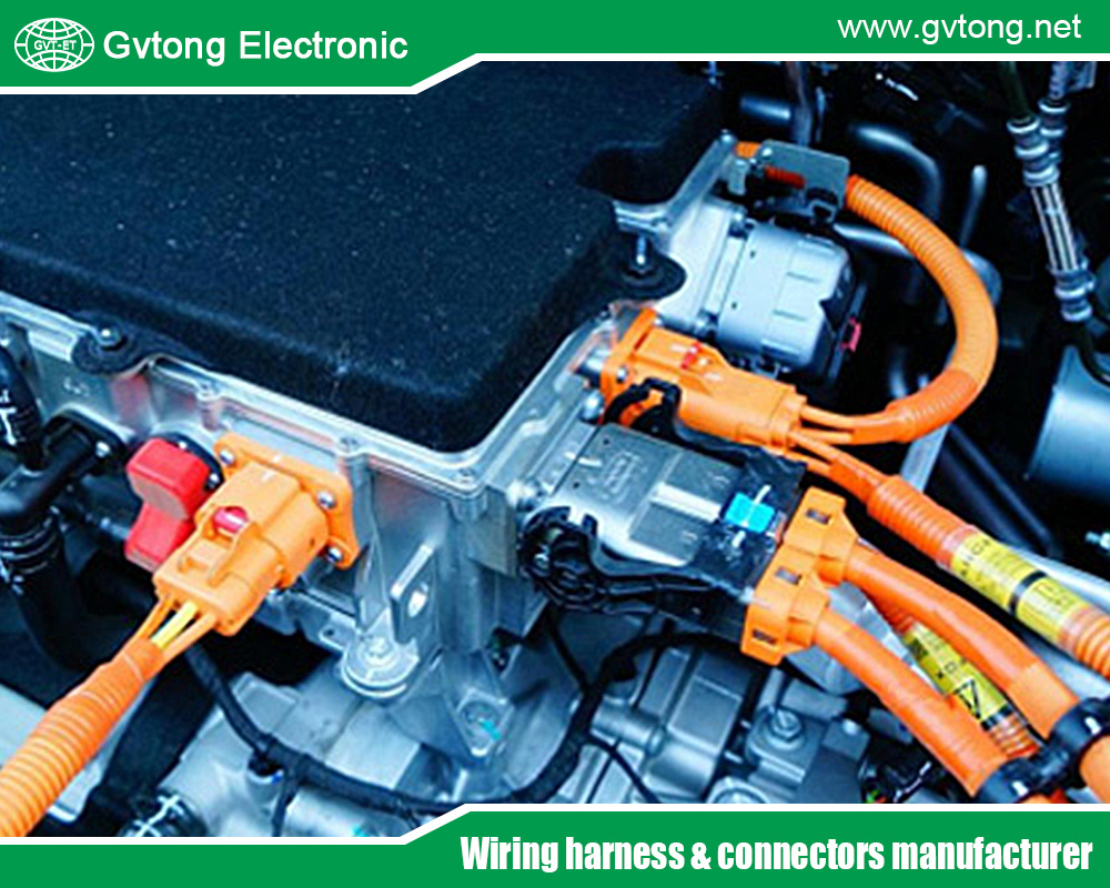
How to Optimize the Heat Dissistance Performance of Automotive High-Voltage Connectors Through Design
The relentless drive toward vehicle electrification has turned the automotive high-voltage (HV) connector from a simple component into a critical thermal management frontier. As electric and hybrid vehicles demand faster charging (800V architectures) and higher continuous power output, the currents flowing through these connectors intensify. The fundamental challenge is rooted in physics: power loss (Ploss) in a connection is proportional to the square of the current (II) multiplied by its resistance (RR), expressed as Ploss=I2R. This lost energy manifests as heat. If not meticulously managed, this heat degrades materials, increases resistance further (creating a thermal runaway risk), and ultimately leads to connector failure, system shutdown, or safety hazards.
Therefore, optimizing the heat dissipation performance of an HV connector is not merely an afterthought; it is a core, non-negotiable design imperative from the outset. It requires a holistic, multi-disciplinary strategy that addresses the entire “thermal chain” from the conductive core to the external environment. Here is how engineering teams approach this challenge through deliberate design.
The Foundation: Minimizing Heat Generation at the Source
The most effective thermal strategy is to generate less heat in the first place. This begins with a ruthless focus on minimizing electrical resistance across the entire current path.
- Contact Interface Excellence: The mating point between male and female terminals is the highest-risk zone for resistance. Design optimizations here are paramount:
- Contact Geometry: Moving from simple pin-and-socket designs to advanced geometries like hyperboloid or multi-finger linear contacts. These designs provide multiple, redundant points of contact, distributing current flow and ensuring a stable, low-resistance interface even under vibration.
- Contact Force: Designing for high, consistent normal force. Sufficient spring force within the female terminal ensures intimate metal-to-metal contact, breaking through surface oxides and maintaining a low-resistance path. This force must be calibrated to remain effective over the connector’s lifetime, accounting for material stress relaxation at high temperatures.
- Material and Plating: Selecting high-conductivity copper alloys (e.g., copper-chromium, copper-beryllium) and superior plating. Silver plating is often preferred over tin for HV applications due to its higher conductivity, better corrosion resistance, and stability at elevated temperatures. Its lower resistance directly translates to less I2RI2R heating.
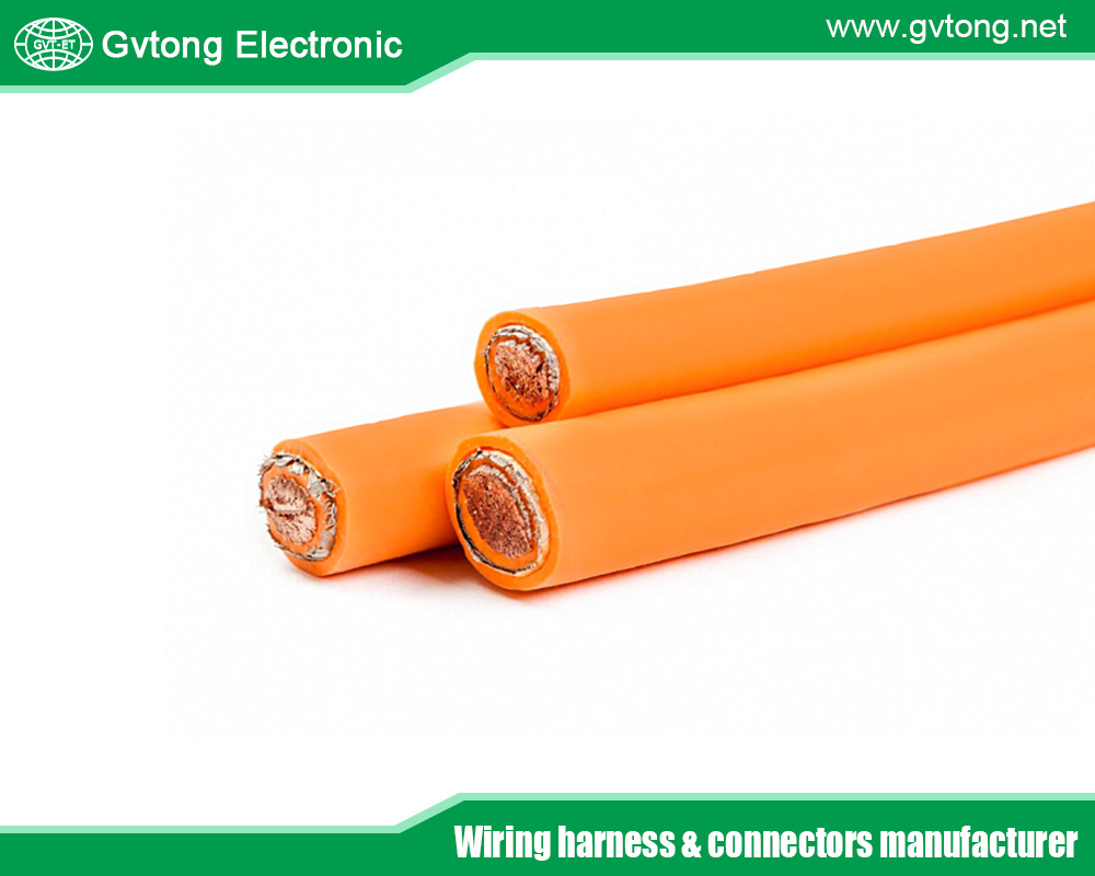
- Conductor and Terminal Bulk: Upsizing the conductive cross-section (both the terminal and the crimped wire) reduces bulk resistance. This involves a careful trade-off between weight, cost, and spatial constraints, but it remains a fundamental lever for heat reduction.
Material Science: Engineering the Thermal Pathway
Once heat is generated, the connector’s materials must manage it effectively. This involves a dual focus: conducting heat away from hotspots and insulating electrically.
- Thermally Conductive, Electrically Insulating Housings: The plastic housing must serve two masters. Advanced engineering thermoplastics like Polyphenylene Sulfide (PPS) or Polyphthalamide (PPA) are standards for their high-temperature stability. To enhance their thermal conductivity, they are compounded with ceramic fillers (e.g., alumina, boron nitride). These fillers create microscopic pathways for heat to flow through the insulating plastic, allowing heat from the internal terminals to be conducted outward to the connector shell or an attached cooling plate.
- Thermal Interface Materials (TIMs): At the interface between the connector housing and a cooling structure (e.g., a cold plate on the battery pack or inverter), design engineers specify TIMs. These can be gap-filling pads, thermally conductive greases, or phase-change materials. Their role is to eliminate insulating air gaps, providing a low-thermal-resistance bridge to shunt heat into a larger, active, or passive cooling system.
Mechanical Architecture for Maximum Heat Rejection
The physical design of the automotive high-voltage connector dictates its surface area and thermal coupling to the environment—key factors in convective and conductive cooling.
- Maximizing Surface Area: Incorporating cooling fins or a corrugated shell design into the connector housing. This increases the surface area in contact with the ambient air (or coolant), significantly enhancing passive convective heat dissipation. This is analogous to the heatsink on a computer CPU.
- Integration with System Cooling: The most advanced designs move beyond passive air cooling. Connectors can be designed with:
- Integrated Cold Plates: The connector housing has a flat, machined surface designed to bolt directly onto a liquid-cooled cold plate, turning the connector into an actively cooled component.
- Direct Liquid Cooling: For extreme applications, such as ultra-fast-charging ports or inverter output stages, connectors are being developed with internal micro-channel cooling. Coolant is circulated through passages molded or machined within the connector body itself, removing heat at the very source.
Holistic System Integration and Simulation
A connector does not operate in isolation. Its thermal performance is inextricably linked to its environment.
- Harness and System Integration: The thermal design must consider the entire cable assembly. Using cables with higher-temperature, thermally conductive insulation can help move heat along the wire away from the connector. Furthermore, routing harnesses away from other heat sources (e.g., exhaust, power electronics) prevents ambient temperature exacerbation.
- Predictive Thermal Simulation: Long before a physical prototype is built, engineers use Finite Element Analysis (FEA) for computational fluid dynamics and thermal modeling. These tools simulate current loads, ambient conditions, and material properties to predict temperature rises and identify hotspots in the 3D model. This allows for iterative optimization of terminal design, housing geometry, and material selection in the virtual space, saving immense cost and time.
Validation: Proving Performance Under Extreme Duress
Design optimization must be validated through rigorous, standardized testing that mirrors a vehicle’s 15-year service life condensed into weeks or months.
- Temperature Rise Test: The cornerstone test. A connector is subjected to its maximum rated current in a controlled ambient temperature chamber. The steady-state temperature rise of the terminals is measured and must stay within strict limits (e.g., per LV214 or USCAR-2 standards) to prevent material degradation.
- Thermal Cycling and Shock: The connector is cycled hundreds of times between extreme high and low temperatures (e.g., -40°C to +125°C or 140°C) while electrically loaded. This tests the stability of the contact interface and the integrity of materials against expansion/contraction stresses.
- Current Cycling Test: Simulating real-world driving, the connector undergoes repeated cycles of high current (simulating acceleration) and lower current. This tests for degradation mechanisms like fretting corrosion and stress relaxation at the contact point.
The Future: Intelligent Thermal Management
The next frontier in connector design moves from passive dissipation to active, intelligent management. Smart Connectors with embedded micro-sensors can provide real-time data on terminal temperature, contact resistance, and current flow. This data can be fed to the vehicle’s Battery Management System (BMS) or vehicle control unit, which could proactively derate power or alert the driver/diagnostic system if a connection is approaching its thermal limit, enabling predictive maintenance and enhanced safety.
Conclusion
Optimizing the heat dissipation of an automotive high-voltage connector is a complex, systemic engineering endeavor. It requires a cascade of deliberate choices, from the atomic-level selection of plating materials to the macro-level design of cooling interfaces. Success is achieved not by a single silver bullet, but by the synergistic integration of low-resistance contact design, thermally engineered materials, architecture for maximum heat rejection, and rigorous system-aware validation.
As electric vehicles push the boundaries of power and charging speed, the thermal performance of the humble connector will remain a decisive factor in overall system reliability, efficiency, and safety. The connector, therefore, evolves from a passive link into an active, optimized thermal manager—a critical enabler in the electrified automotive future. Through intelligent design, engineers ensure these components not only carry the spark of innovation but do so with unwavering coolness under pressure.
For more about how to optimize the heat dissistance performance of automotive high-voltage connectors through design, you can pay a visit to Gvtong at https://www.gvtong.net/ for more info.
-

GM Series – Positive and negative junction box – inclined port
-

GR Series-19-core 16# circular signal connector
-

Signal connector-waterproof, double row, 18/26 core
-

GH280 Series-2-core plastic high voltage connector
-

GH Serie-GMV3-2-core plastic high voltage connector
-

Automotive FAKRA Connector – Board End, DC to 3GHz From RF Connectors And Cables Manufacturer In China
-

Energy storage connector 5.7mm
-

GE Series-10PIN Right Angle Connector Socket